Thermoforming Machine Having Platen Locks and Method

Inactive Publication Date: 2013-05-16
IRWIN RES & DEV
View PDF5 Cites 25 Cited by
  • Summary
  • Abstract
  • Description
  • Claims
  • Application Information

AI Technical Summary

Benefits of technology

[0004]A thermoforming machine is provided with a platen lock mechanism that reduces a need to further increase structural load capacity of a frame and plate drive linkages on a thermoforming machine.

Problems solved by technology

Where large arrays of articles are provided on die plates on a platen, the surface area subject to pneumati

Method used


Image

  • Thermoforming Machine Having Platen Locks and Method
  • Thermoforming Machine Having Platen Locks and Method
  • Thermoforming Machine Having Platen Locks and Method

Examples


Embodiment Construction

[0055]This disclosure is submitted in furtherance of the constitutional purposes of the U.S. Patent Laws “to promote the progress of science and useful arts” (Article 1, Section 8).

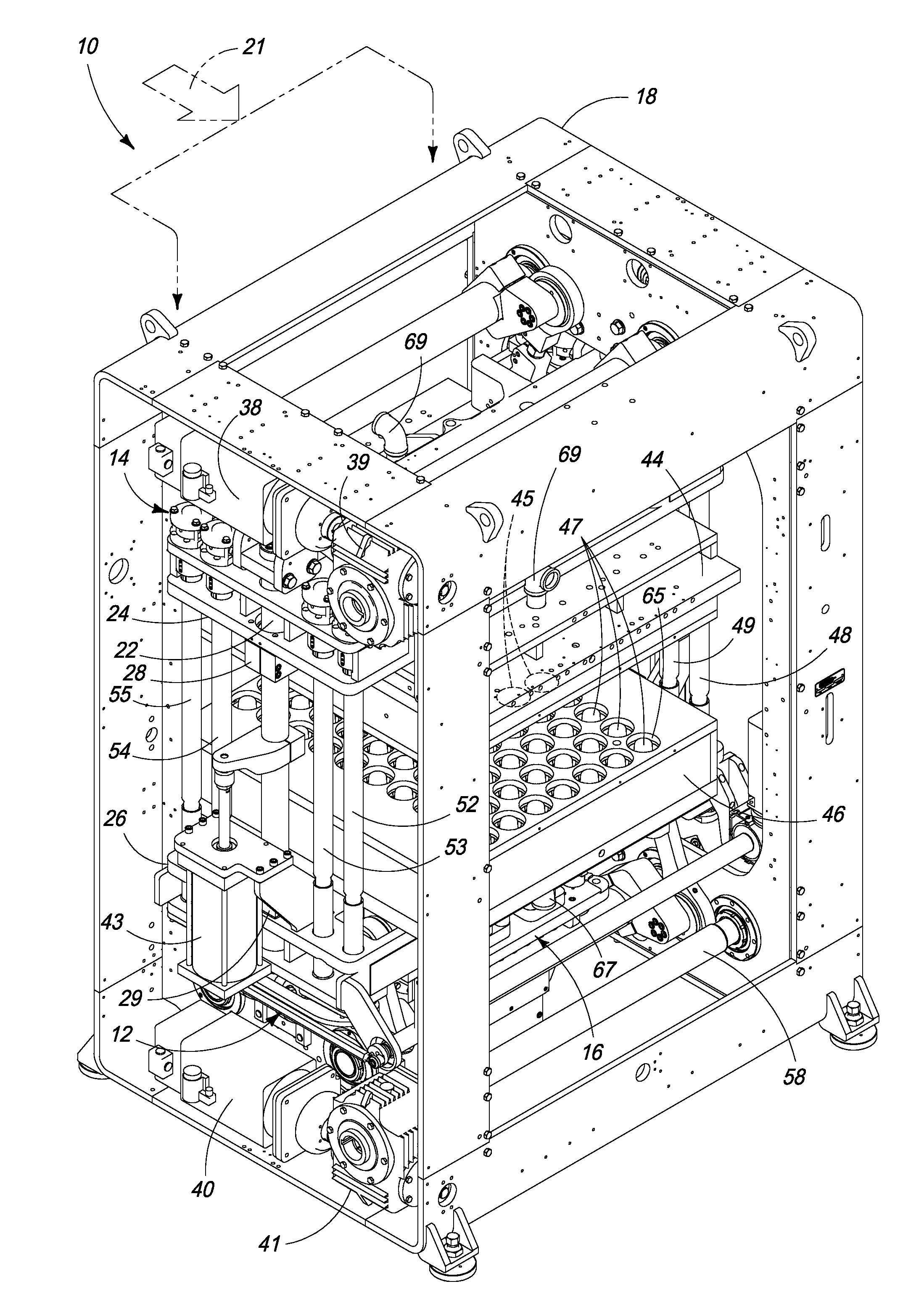
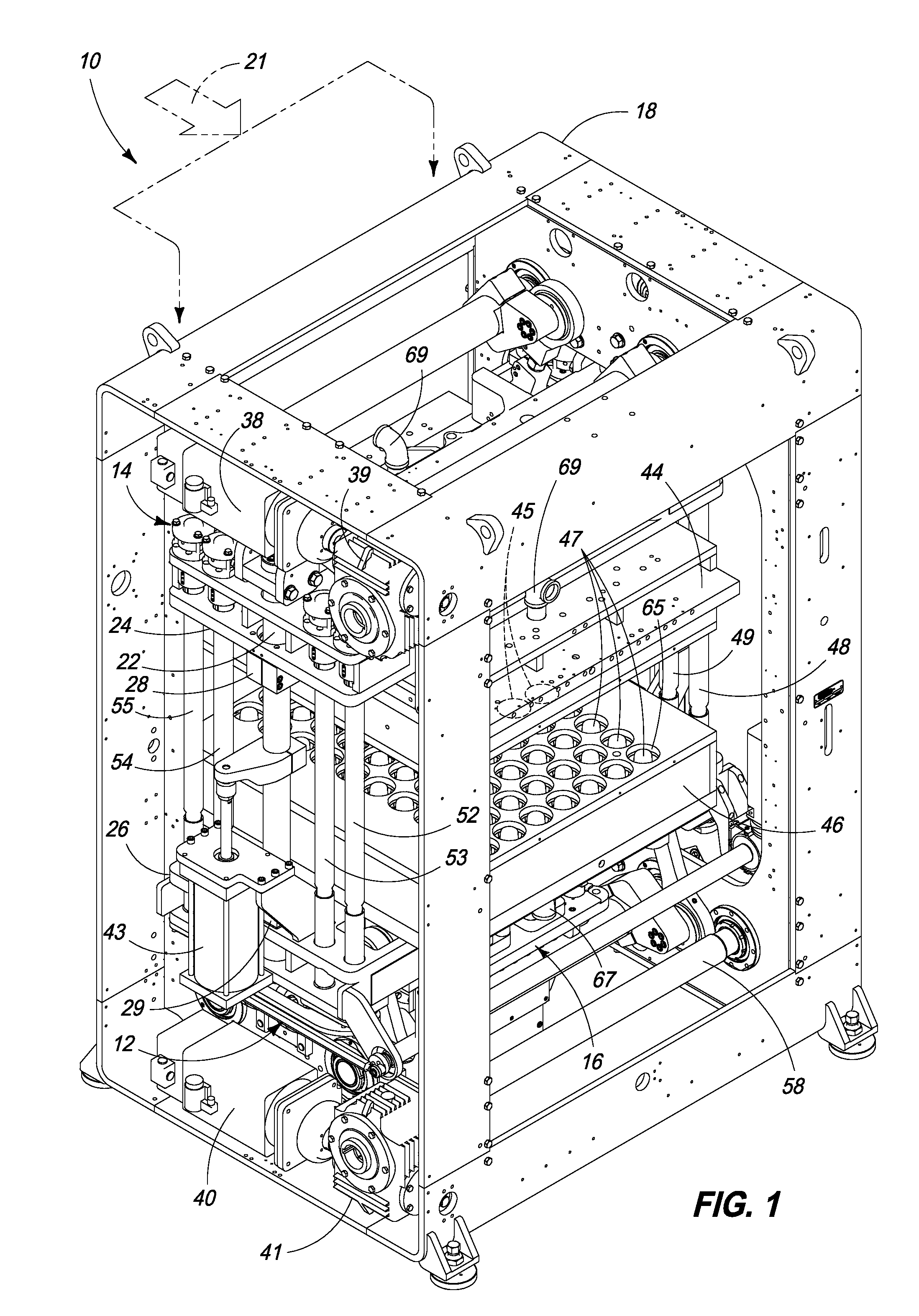
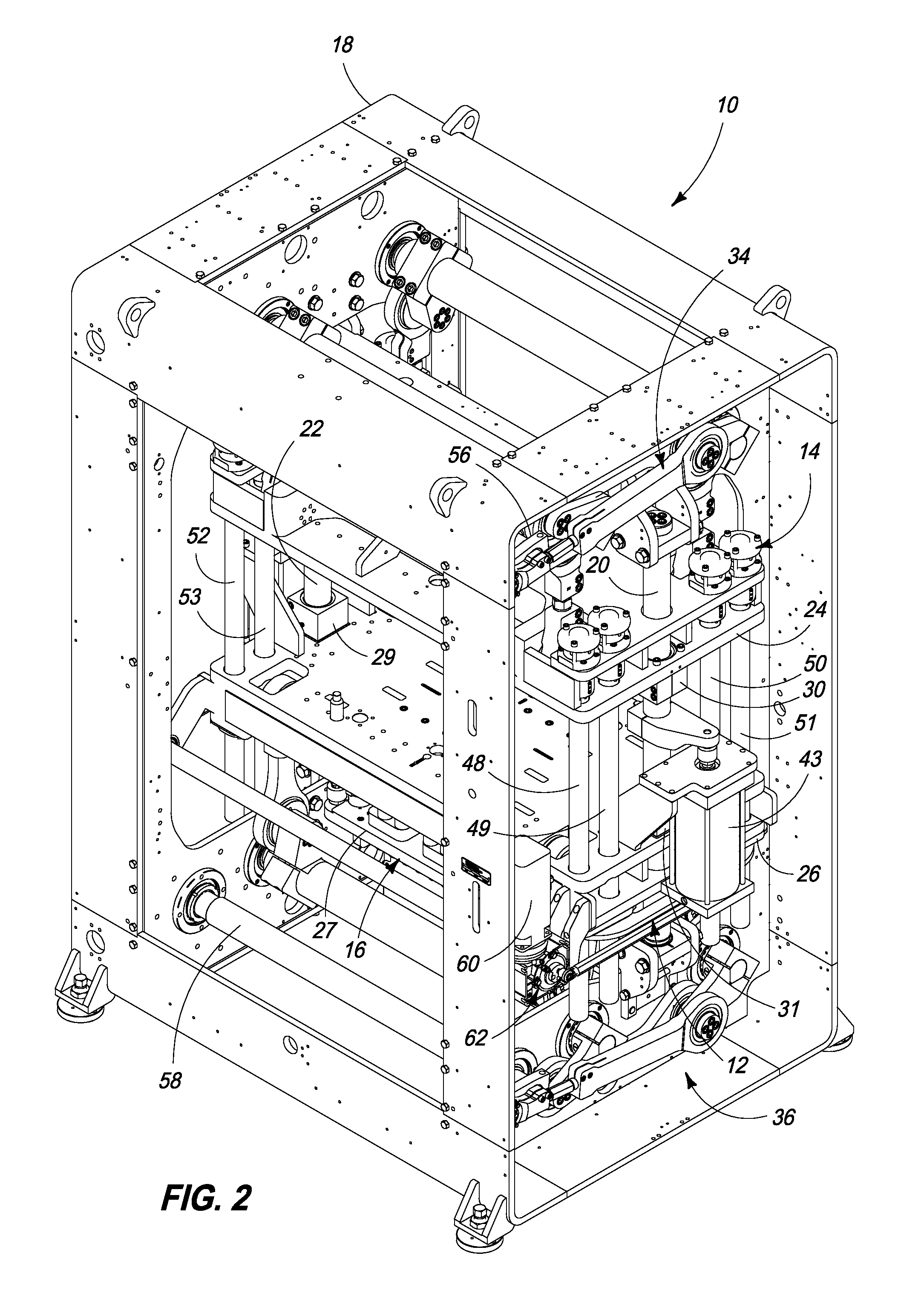
[0056]Attention is now directed towards embodiments of the device. FIGS. 1 and 2 are left and right perspective views illustrating a thermoforming machine 10 with a platen lock assembly 12 in accordance with an embodiment. More particularly, thermoforming machine 10 includes a structural frame 18, stationary die posts 20 and 22 supported by frame 18, an upper platen 24, and a lower platen 26. Upper platen 24 and lower platen 26 are supported for vertical reciprocation via pairs of respective bronze bushings 28, 29 and 30, 31, respectively. A kinematic drive linkage drives upper platen 24 and lower platen 23 using upper kinematic linkage assembly 34 and lower kinematic linkage assembly 36, respectively, each driven by a respective servo motor 38 and 40 (see FIG. 1) via gearboxes 39 and 41, respectively. A ...


PUM

PropertyMeasurementUnit
Thicknessaaaaaaaaaa
Pressureaaaaaaaaaa
Diameteraaaaaaaaaa

Abstract

A thermoforming machine is provided having a frame, a first platen, a second platen, a platen load shaft, and a load shaft latch. The first platen supports a first mold. The second platen supports a complementary second mold and is carried by the frame for movement toward and away from the first platen to engage and disengage with the first mold. The platen load shaft has a lock ledge with an engagement surface transverse to the load shaft. The load shaft is supported by the frame and extends between the first platen and the second platen. The load shaft latch has an engagement surface transverse to a central axis of the load shaft and is movable to engage and disengage the lock ledge transverse engagement surface. A method is also provided.

Description

CROSS REFERENCE TO RELATED APPLICATION[0001]This application claims priority to U.S. Provisional Patent Application Ser. No. 61 / 559,231 which was filed on Nov. 14, 2011, the entirety of which is incorporated by reference herein.TECHNICAL FIELD[0002]This disclosure pertains generally to thermoforming apparatus. More particularly, this disclosure relates to lock or latch mechanisms for securing together opposed platens and dies when male dies are received into respective female mold cavities as pneumatic pressure is applied on a male mold side of a heated thermoformable sheeting during an article forming operation.BACKGROUND OF THE INVENTION[0003]The use of large tonnage thermoforming frames and drive mechanisms is known where pneumatic pressure is being applied to a heated sheet of thermoformable material during an article forming operation. Where large arrays of articles are provided on die plates on a platen, the surface area subject to pneumatic pressure generates very large loads...

Claims


Application Information

Patent Timeline
IPC IPC(8): B29C51/20
CPCB29C51/20B29C51/082B29C2791/007B29C51/38B29C2791/006B29C51/18
Inventor VANTREASE, DALE L.
Owner IRWIN RES & DEV
Why Eureka
Try Eureka