
Flexible Tier Data Center

a data center and flexible technology, applied in the field of flexible tier data centers, can solve the problems of tier 1 data centers being least robust but least expensive, data center capacity plans, normally driving construction, getting less reliable, and being more susceptible to change. , to achieve the effect of significant energy and other cost savings, high cost of building an efficient data center

Inactive Publication Date: 2013-05-16
R2 SOLUTIONS
View PDF12 Cites 14 Cited by
  • Summary
  • Abstract
  • Description
  • Claims
  • Application Information

AI Technical Summary

Benefits of technology

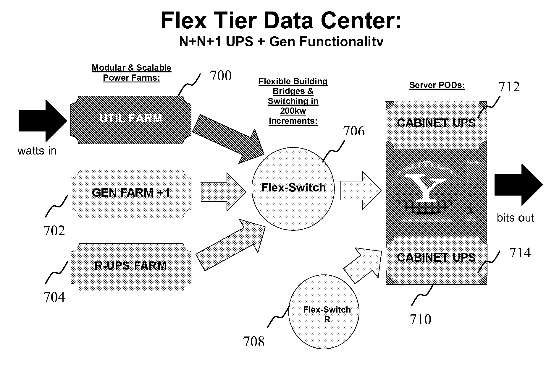
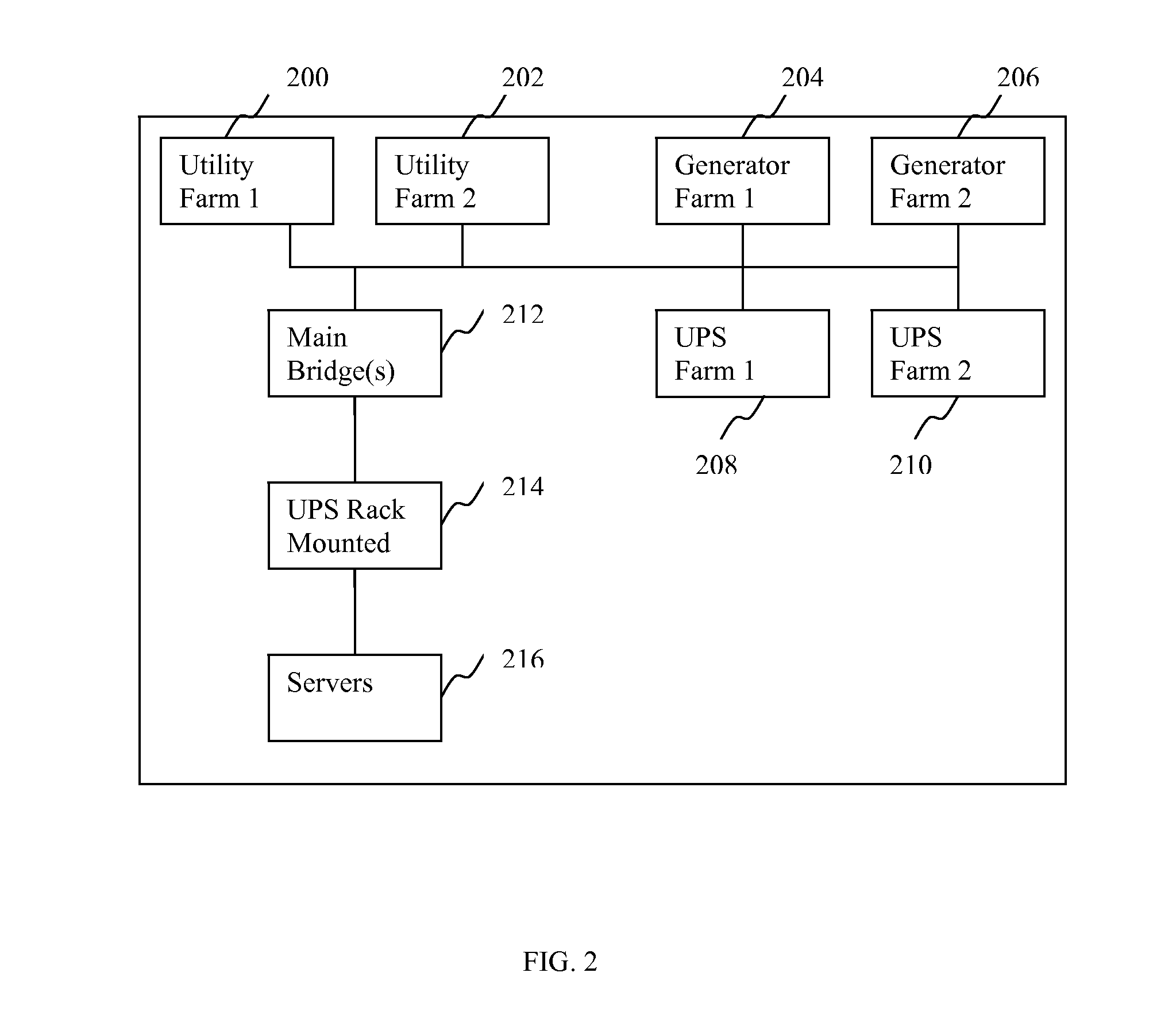
The patent text describes a server cooling system and a data center that includes a flex-switch and various utility farms, such as power distribution units and UPS farms, to improve cooling efficiency for servers. The flex-switch can be expanded after construction of the system is complete to include additional utility farms, generator farms, and UPS farms. Overall, the system and center provide improved cooling for servers and increased flexibility for future expansion.

Problems solved by technology

The availability requirement of applications hosted in a data center may change over time.
On the other hand, Tier 1 data centers are least robust but least expensive and may be suitable for less critical applications.
Data center capacity plans, which normally drive construction, get less reliable and are more susceptible to change.
Shorter build cycles of a data center saves costs.
Longer build cycles, however, may cause unavailability of longer capacity plan.
Stranded and idle data center capacity creates a less optimal Power Usage Effectiveness (PUE) curve and is the equivalent of having an idle factory.
However, often times, the progress of the Pre-Construction activities may be unpredictable and the schedule may slip.
The cost of the Pre-Construction activities, however, is typically a small percentage of the total project cost.
The smaller UPS units save power and upfront cost.
While the performance of servers is improving, the power consumption of servers is also rising despite efforts in low power design of integrated circuits.
Processors are only part of a server, however; other parts in a server such as storage devices consume additional power.
As a result, server racks can produce very concentrated heat loads.
The heat collectively generated by densely populated racks can have an adverse effect on the performance and availability of the equipment installed in the racks, since they rely on the surrounding air for cooling.
The cost of building an efficient data center normally is high.

Method used


Image

  • Flexible Tier Data Center
  • Flexible Tier Data Center
  • Flexible Tier Data Center

Examples


Embodiment Construction

[0032]The following example embodiments and their aspects are described and illustrated in conjunction with apparatuses, methods, and systems which are meant to be illustrative examples, not limiting in scope.

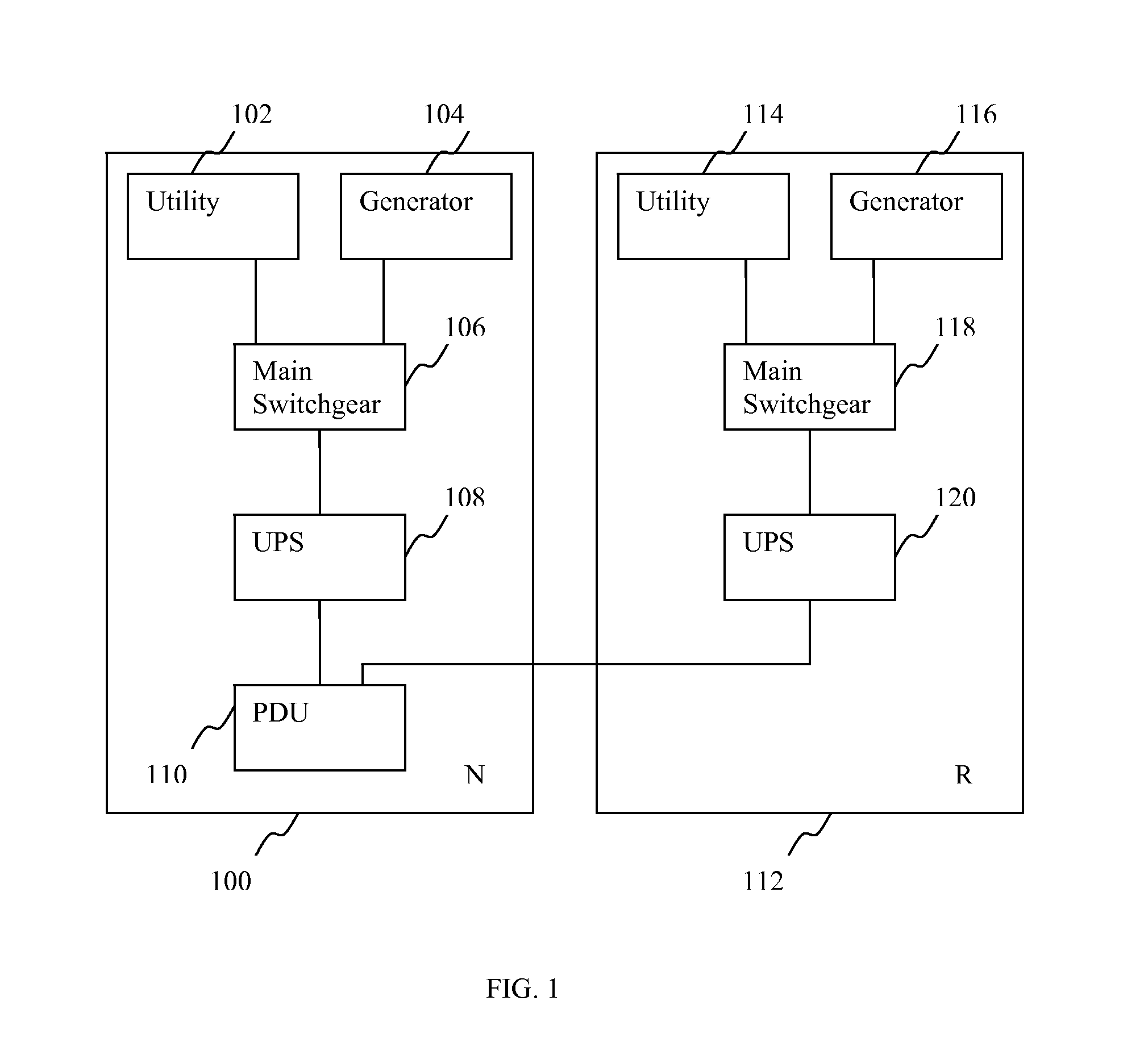
[0033]FIG. 1 illustrates an example N+1 electrical power system in a data center. N+1 means that if the electrical power load can be supplied by N modules, the installation will contain at least N+1 electrical power modules wherein the +1 module acts as an independent backup component. The backup component may not actively participate in the normal system operation. In FIG. 1, module 100 provides electrical power to server racks housing servers and other equipment in a data center. Electrical power utility 102 and a power generator 104 are coupled with a main switchgear 106. In some embodiments, local electrical power utility is supplying electrical power to the main switchgear 106. In some other embodiments, the electrical power utility may not be available and the generator 1...


PUM


Abstract

A server cooling system includes: a flex-switch with one or more flexible building bridges; one or more utility farms coupled with the flex-switch; a power distribution unit operably connected to the flex-switch; and a server POD including one or more racks operably connected to the power distribution unit. The flex-switch is configurable to include additional utility farms, one or more generator farms, and one or more UPS farms.

Description

CROSS-REFERENCE TO RELATED APPLICATIONS[0001]This application is a non-provisional of, and claims priority from, U.S. Provisional Patent Application No. 61 / 450,980, filed on Mar. 9, 2011.FIELD OF THE INVENTION[0002]The present disclosure relates generally to flexible tier data centers and in one example for a data center that is scalable and configurable for various availability requirements.BACKGROUND OF THE INVENTION[0003]The rise of cloud computing wherein services and storage are provided over the Internet enables providing shared resources, software, and information to desktop computers, mobile devices and other devices on demand. Server virtualization enables partitioning one physical server computer into multiple virtual servers. Each virtual server appears to be the same as a physical server and is capable of functioning as a full-fledged server. The combination of cloud computing and server virtualization is powerful in supplying on-demand computing utility and is flexible ...

Claims


Application Information

Patent Timeline
Patent Type & Authority Applications(United States)
IPC IPC(8): G06F1/20G06F1/18
CPCG06F1/189G06F1/20
Inventor BIANCULLI, BARRYHOLT, NORMANIMMEL, JEREMYNOTEBOOM, SCOTTROBISON, ALBERT DELLSUAREZ, JESUS
Owner R2 SOLUTIONS
Learn More