
Cascaded h-bridge medium voltage drive, power cell and bypass module thereof

a medium voltage drive and cascade technology, applied in the field of variable frequency drives, can solve the problems of economic loss or aggravation of accidents, less reliability of drive systems, and more complicated and relative cost of system design, and achieve excellent cost advantage for high power, low loss, and simple circuit structure

Active Publication Date: 2013-05-16
DELTA ELECTRONICS (SHANGHAI) CO LTD
View PDF5 Cites 57 Cited by
  • Summary
  • Abstract
  • Description
  • Claims
  • Application Information

AI Technical Summary

Benefits of technology

The present patent application provides a cascaded H-Bridge medium voltage drive, power cell, and bypass module that solves problems of high cost, large size, and complexity of prior bypass circuits. The bypass circuit is designed to switch on when the major circuit module malfunctions and can bypass it to ensure a normal operation of the cascaded H-Bridge medium voltage drive with low loss and a simple circuit structure. This results in a low-cost advantage for high power medium voltage drive systems.

Problems solved by technology

In particular, under the circumstance that the operation reliability of medium-voltage / high-voltage devices is not high enough while the cost thereof is expensive, such a problem has been well resolved in recent years by means of cascading low-voltage power cells.
With so many power cells, once a malfunction occurs in a certain power cell, the whole drive system may fail and be unable to keep operating if there isn't any proper solution, which may result in an economic loss or an aggravation of accident.
Increasing of the number of power cells makes the drive system less reliable.
Chinese Patent Application No. 201010218945.2 discloses a unit bypass circuit of unit cascaded H-Bridge medium voltage drive, which is inefficient since a mechanical-operated switch blade therein needs to be closed manually when the power cell malfunctions, and then the mechanical-operated switch blade needs to be opened after the malfunctioned power cell is replaced.
However, it will be more complicated and relative expensive for the system design in high power variable-frequency drive due to a large size and a high cost of the contactor.
In summary, the bypass circuit in the cascaded H-Bridge medium voltage drive in related arts has disadvantages such as being expensive and large-sized, hence needs to be further improved.

Method used


Image

  • Cascaded h-bridge medium voltage drive, power cell and bypass module thereof
  • Cascaded h-bridge medium voltage drive, power cell and bypass module thereof
  • Cascaded h-bridge medium voltage drive, power cell and bypass module thereof

Examples


first embodiment

The First Embodiment

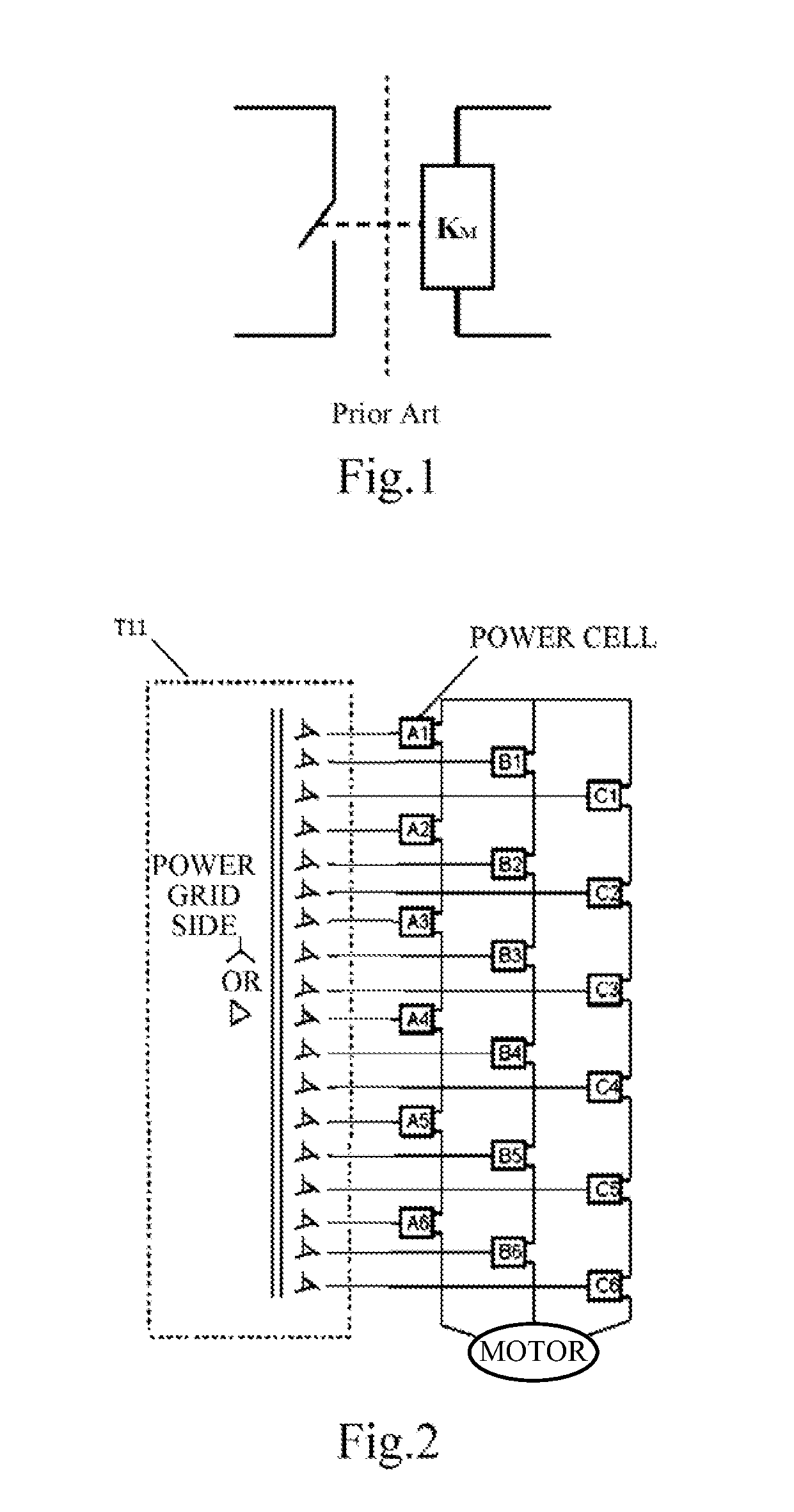
[0057]As shown in FIG. 2, a cascaded H-Bridge medium voltage drive is provided according to the first embodiment of the present application, comprising a phase shifting transformer T11 and at least one power cell.

[0058]As an embodiment shown in FIG. 2, it is a schematic view showing a cascaded H-Bridge medium voltage drive of 6 kV with 18 power cells. The cascaded H-Bridge medium voltage drive comprises the phase shifting transformer T11 and 18 power cells which constitute three phase output of the cascaded H-Bridge medium voltage drive, wherein, each phase comprises 6 power cells connected in series and outputs a high voltage.

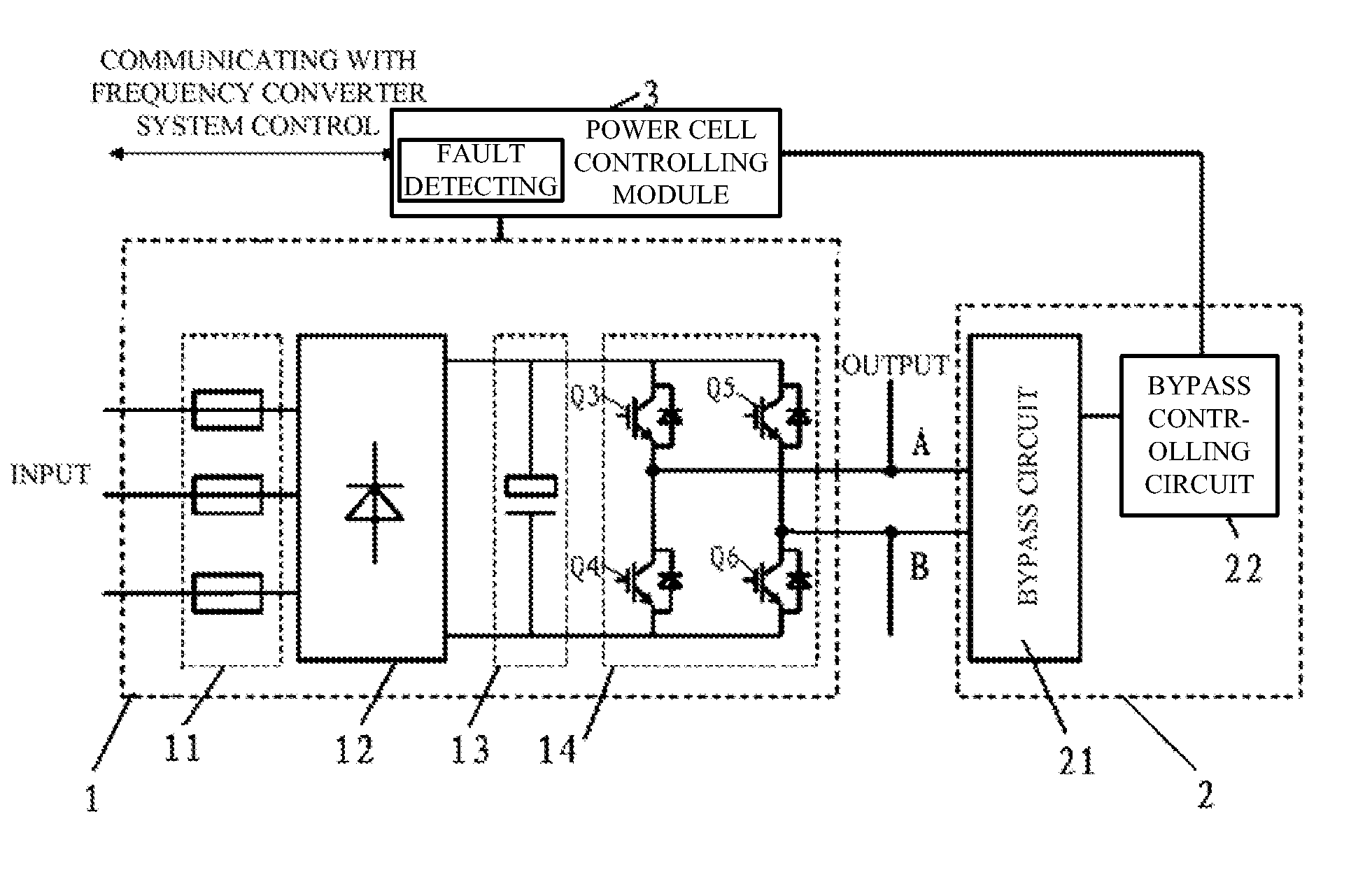
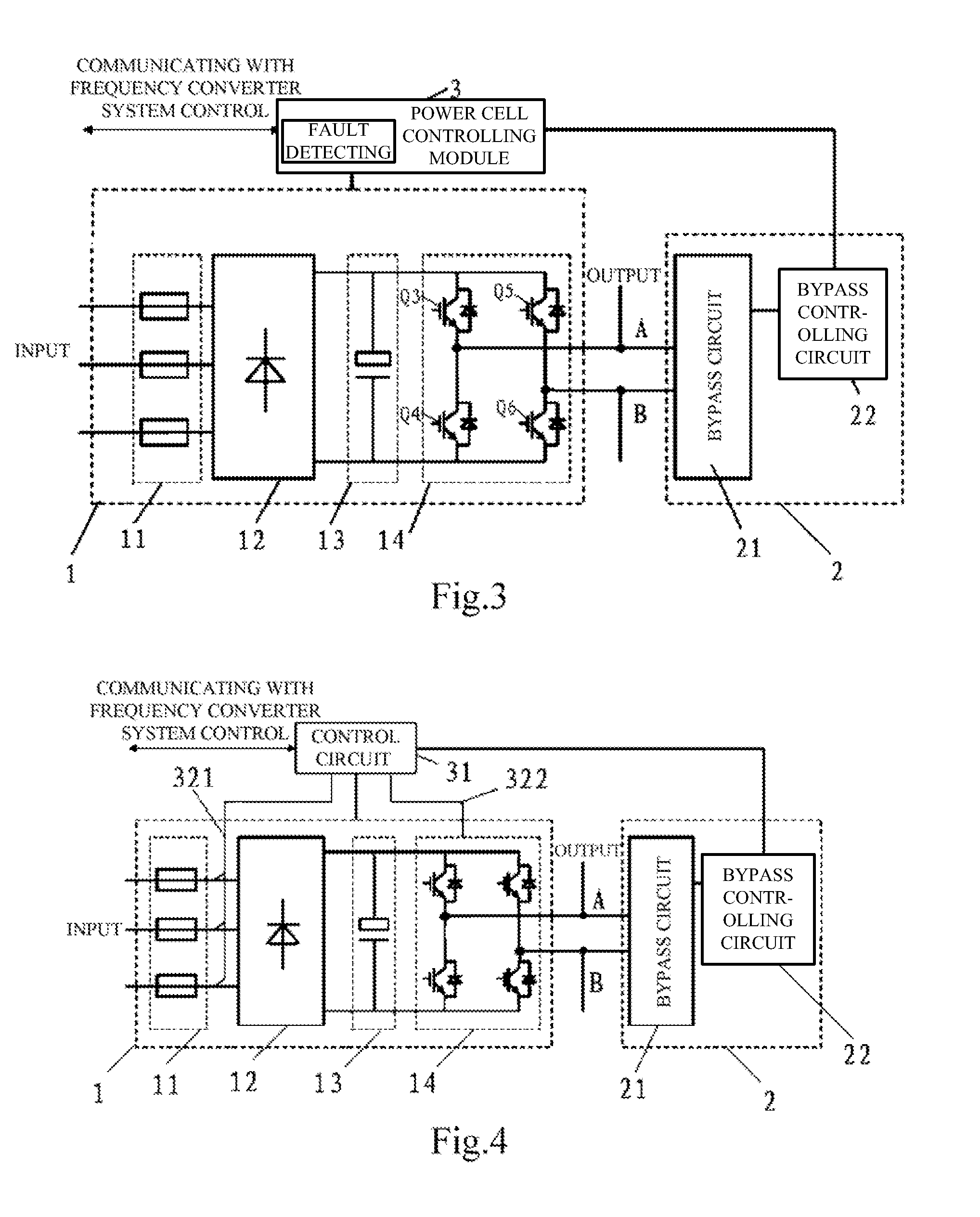
[0059]FIG. 3 is a circuit diagram of a power cell shown in FIG. 2 with a bypass module 2. The power cell comprises a major circuit module 1, a bypass module 2 and a power cell controlling module 3. As an embodiment, the major circuit module 1 includes a fuse 11, a rectifier 12, a bus capacitor 13 and an H-Bridge inverter (inverter bridge ar...

second embodiment

The Second Embodiment

[0067]As an embodiment, a bypass module of power cell in cascaded H-bridge medium voltage drive according to the second embodiment of the present application comprises a bypass circuit 21 and a bypass controlling circuit 22.

[0068]The bypass circuit 21 includes a first switch element, a second switch element, a first diode and a second diode.

[0069]The bypass circuit 21 has a first input end and a second input end, wherein the first input end is electrically connected with the first output end of the major circuit module 1, and the second input end is electrically connected with the second output end of the major circuit module 1. When the major circuit module 1 malfunctions and the bypass circuit 21 is switched on for operation, one of the first switch element and the second switch element and one of the first diode and the second diode in the bypass circuit 21 turn on to bypass the major circuit module 1 of corresponding power cell.

[0070]The first and second swi...

third embodiment

The Third Embodiment

[0088]As an embodiment, a bypass module 2 provided by the present application comprises a bypass circuit 21 and a bypass controlling circuit 22. The bypass circuit 21 includes a first IGBT Q1, a second IGBT Q2, a first diode D1, a second diode D2 and an absorption circuit 211.

[0089]As an embodiment, the absorption circuit 211 is an absorption capacitor C1. As shown in FIG. 12, taking the bypass circuit 21 shown in FIG. 5 as an example, the absorption capacitor C1 is connected in parallel across the bypass circuit 21, that is, across the bridge arm formed by the first diode D1 and the second diode D2 being connected in series.

[0090]Referring to FIG. 13, which is a schematic view showing an embodiment of connection between the bypass circuit 21 shown in FIG. 12 and the major circuit module 1, two output ends of the major circuit module 1 are electrically connected with two input ends of the bypass circuit 21, respectively.

[0091]As an embodiment, the power cell also...


PUM


Abstract

The present application relates to a cascaded H-Bridge medium voltage drive, a power cell, and a bypass module thereof, wherein the bypass module is configured for bypassing a major circuit module of the power cell, while the major circuit module comprises a fuse, a rectifier, a bus capacitor and an H-Bridge inverter, two points led from the H-Bridge inverter being configured as a first output end and a second output end; a bypass circuit comprises a first bridge arm and a second bridge arm; a point led from the first bridge arm is configured as a first input end of the bypass circuit, a point led from the second bridge arm is configured as a second input end of the bypass circuit, and the first input end is electrically connected with the first output end, the second input end is electrically connected with the second output end.

Description

CROSS REFERENCE TO RELATED APPLICATIONS[0001]The present application is based upon and claims priority under 35 U.S.C. §119(a) to prior Chinese Patent Application No. 201110357786.9 filed on Nov. 11, 2011, the entire contents of which are incorporated herein by reference.FIELD OF THE INVENTION[0002]The present application relates to the technical field of Variable-frequency Drive (VFD), and more particularly to a cascaded H-Bridge medium voltage drive, a power cell and a bypass module thereof.BACKGROUND OF THE INVENTION[0003]The use of high power variable-frequency drive has become increasingly popular with the rapid development of modern power electronic technology and microelectronic technology. In particular, under the circumstance that the operation reliability of medium-voltage / high-voltage devices is not high enough while the cost thereof is expensive, such a problem has been well resolved in recent years by means of cascading low-voltage power cells. Therefore, the applicatio...

Claims


Application Information

Patent Timeline
Patent Type & Authority Applications(United States)
IPC IPC(8): H02M5/458
CPCH02M7/49H02M1/32H02M2001/325H02M5/4585H02M1/325H02M1/0085
Inventor GAN, HONGJIANZHONG, QINGLONG
Owner DELTA ELECTRONICS (SHANGHAI) CO LTD
Learn More