Rotor and motor

a technology of rotor and motor, which is applied in the direction of magnetic circuit rotating parts, piston pumps, magnetic circuit shape/form/construction, etc., can solve the problems of increasing costs, requiring time and labor for coupling, etc., and achieves the effect of increasing the output of the motor and increasing the number of components

Active Publication Date: 2013-05-16
DENSO CORP
View PDF21 Cites 17 Cited by
  • Summary
  • Abstract
  • Description
  • Claims
  • Application Information

AI Technical Summary

Benefits of technology

[0005]A first object of the present invention is to provide a rotor that can contribute to increasing an output of a motor while suppressing an increase in the number of components, and a motor including such a rotor.

Problems solved by technology

This requires time and labor for the coupling and increases costs.

Method used


Image

  • Rotor and motor
  • Rotor and motor
  • Rotor and motor

Examples


first embodiment

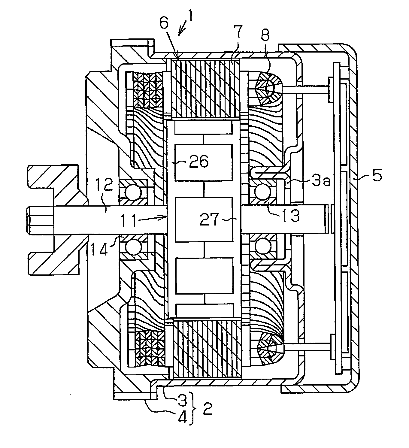
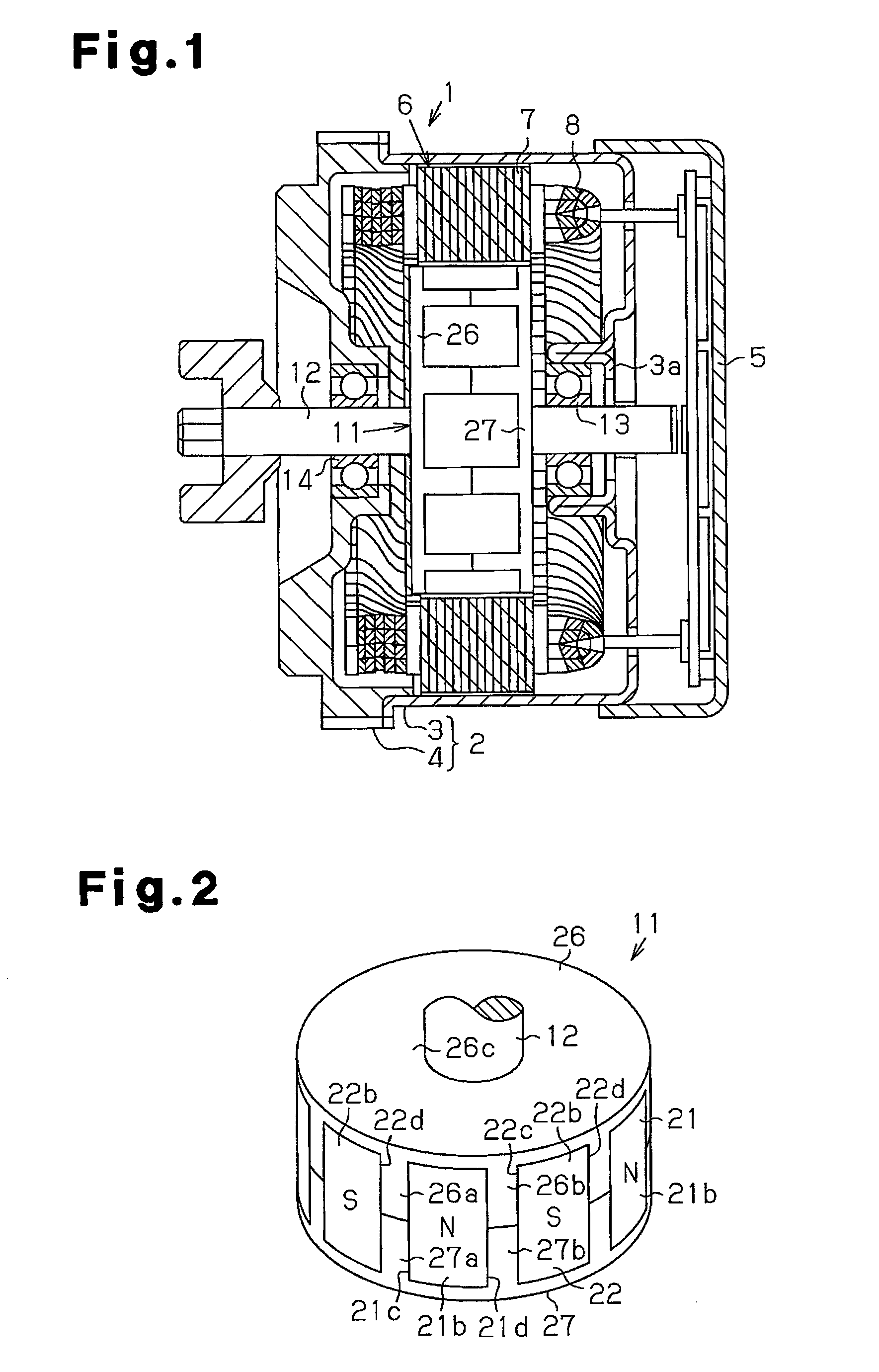
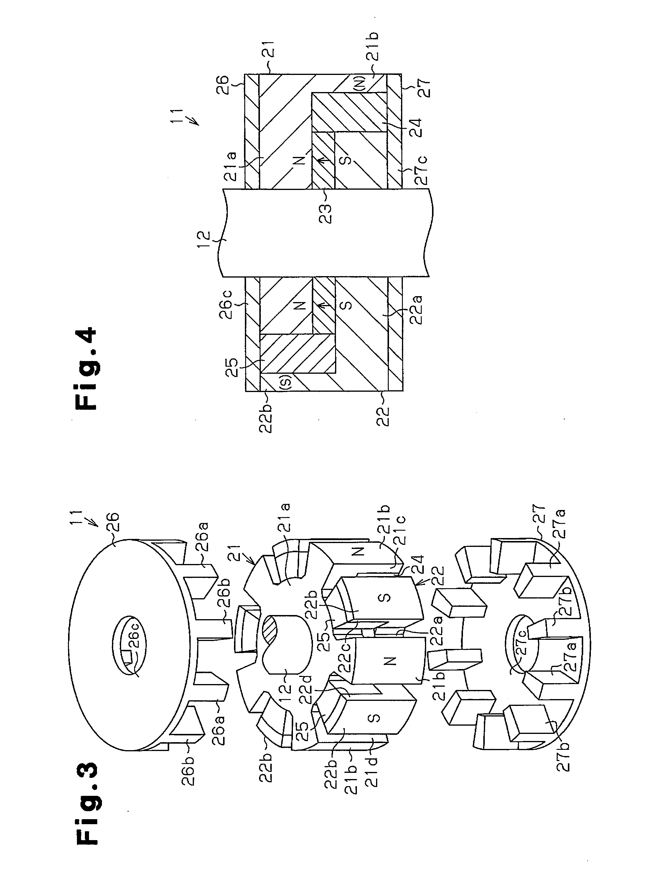
[0066]A first embodiment of the present invention will be described below with reference to FIG. 1 to FIG. 4.

[0067]As shown in FIG. 1, a motor casing 2 of a motor 1 includes a cylindrical housing 3 formed in a bottomed cylinder shape, and a front end plate 4 that closes an opening of the cylindrical housing 3 on a front side (left side in FIG. 1). Further, a circuit containing box 5 that contains a power circuit such as a circuit board and the like is attached to an end portion of the cylindrical housing 3 on a rear side (right side in FIG. 1).

[0068]A stator 6 is fixed to an inner circumferential surface of the cylindrical housing 3. The stator 6 includes an armature core 7 including a plurality of teeth extending radially inward, and a segment conductor (SC) wire 8 which is wound around each tooth of the armature core 7.

[0069]A rotor 11 of the motor 1 includes a rotation shaft 12, and is arranged inside the stator 6. The rotation shaft 12 is a metal shaft made of a non-magnetic bod...

second embodiment

[0092]Next, the second embodiment of the present invention will be described with reference to FIG. 5 to FIG. 7. Notably, for convenience of description, same configurations as the first embodiment will be given with the same reference signs as the first embodiment, and the description thereof will be omitted.

[0093]As shown in FIG. 5 to FIG. 7, a rotor 11 includes first and second rotor cores 31, 32, a ring magnet 33 as a field magnet (see FIG. 6), and a connecting magnet 34 as an integrated auxiliary magnet. Notably, arrows shown with solid lines in FIG. 5 to FIG. 7 indicate magnetized directions (oriented from S pole toward N pole) of the magnets 33, 34.

[0094]As shown in FIG. 5, the first rotor core 31 has a plurality of first hook-shaped poles 31b (seven in the embodiment) as hook-shaped poles formed on a peripheral portion of a first core base 31a as a core base having a substantially disk shape. Each first hook-shaped pole 31b includes a protruding portion 31c protruded outward...

third embodiment

[0135]A third embodiment of the present invention will be described below in accordance with the drawings.

[0136]As shown in FIG. 21 and FIG. 22, a rotor 111 includes a first and second rotor cores 121, 122, a ring magnet 123 (see FIG. 23) and an auxiliary magnet 124. Notably, arrows shown with solid lines in FIG. 22 and FIG. 23 indicate magnetized directions (oriented from S pole toward N pole) of the respective magnets 123, 124.

[0137]The first and second rotor cores 121, 122 and the ring magnet 123 of the third embodiment are shown in FIG. 21 and FIG. 22. Descriptions for configurations similar to the first and second rotor cores 21, 22 and the ring magnet 23 of the first embodiment will be omitted.

[0138]The rotor 111 of the third embodiment is a rotor with a so-called Randell type structure that uses the ring magnet 123 as a field magnet. The rotor 111 includes first hook-shaped poles 121b that are the N poles and second hook-shaped poles 122b that are the S poles alternately in a...


PUM


Abstract

A rotor includes a first rotor core, a second rotor core, a field magnet, and an auxiliary magnet. The first rotor core includes a first core base and a plurality of first hook-shaped poles. The second rotor core includes a second core base and a plurality of second hook-shaped poles. The first and second hook-shaped poles are alternately arranged in a circumferential direction of the rotor. The field magnet is arranged between the first and second core bases in an axial direction. The field magnet cause the first hook-shaped poles to function as first poles and the second hook-shaped poles to function as second poles. The auxiliary magnet includes at least two interpolar magnet portions, which are integrally formed. Each interpolar magnet portion is arranged in a void between the first hook-shaped pole and the second hook-shaped pole and magnetized in the circumferential direction.

Description

BACKGROUND ART[0001]The present invention relates to a rotor and a motor.[0002]As a rotor used in a motor, a rotor with a Randell-type structure using a so-called permanent magnet field system is known (for example, refer to Japanese Laid-Open Utility Model Publication No. H5-43749), that includes combined rotor cores, each having a plurality of hook-shaped poles in a circumferential direction. A field magnet is arranged between the rotor cores to cause the hook-shaped poles to function alternately different in their magnetic poles.[0003]In a motor that employs the above rotor, an output improvement is desired, while it is also desired to suppress the number of required components.[0004]Further, in the rotor with the Randell-type structure using the permanent magnet field system, in order to achieve high output of the motor, rectifying magnets for rectifying magnetic paths are arranged between the plurality of hook-shaped poles that is arranged alternately in a circumferential direc...

Claims


Application Information

Patent Timeline
Patent Type & Authority Applications(United States)
IPC IPC(8): F04D13/06
CPCH02K1/2706F04D13/06H02K1/30H02K1/2713
Inventor YAMADA, YOJIMORITA, CHIETATEISHI, YOKOFUJII, YUUKIYOKOYAMA, SEIYA
Owner DENSO CORP
Why Eureka
Try Eureka