Motor, vehicle power unit with motor, generator, vehicle wheel bearing with generator

a technology for vehicle power units and generators, which is applied in the direction of electric devices, braking systems, electric devices, etc., can solve the problems of reducing the inability to effectively perform the assistance of a driving force and power recovery, and the dimensions of the motor. achieve the effect of increasing the axial length of the wheel bearing, increasing the motor output, and increasing the axial length of the wheel

Pending Publication Date: 2021-03-11
NTN CORP
View PDF0 Cites 4 Cited by
  • Summary
  • Abstract
  • Description
  • Claims
  • Application Information

AI Technical Summary

Benefits of technology

[0008]A vehicle power unit including a travel assist motor with a power generation function has advantages that it can be received inside a wheel body and that constituting parts around the wheels can be used without change. However, this in turn restricts the dimensions of the motor, making it difficult to increase a motor output and to effectively perform assistance of a driving force and power recovery during braking operation. In order to increase a motor output, it is necessary to increase a wheel axial length of a motor stator core so as to enlarge an area of motor magnetic poles, which, however, makes it difficult to accommodate a motor stator (including the motor stator core and coil ends) within a limited space.

Problems solved by technology

However, this in turn restricts the dimensions of the motor, making it difficult to increase a motor output and to effectively perform assistance of a driving force and power recovery during braking operation.
In order to increase a motor output, it is necessary to increase a wheel axial length of a motor stator core so as to enlarge an area of motor magnetic poles, which, however, makes it difficult to accommodate a motor stator (including the motor stator core and coil ends) within a limited space.
There is an approach involving using a bus bar as wiring connection at coil ends of motor winding coils so as to reduce dimensions of a wiring connection part; however, the conventional approach including disposing a bus bar at an end face of coil ends cannot sufficiently shorten an overall length of a motor stator (a wheel axial length of the motor stator).

Method used


Image

  • Motor, vehicle power unit with motor, generator, vehicle wheel bearing with generator
  • Motor, vehicle power unit with motor, generator, vehicle wheel bearing with generator
  • Motor, vehicle power unit with motor, generator, vehicle wheel bearing with generator

Examples


Embodiment Construction

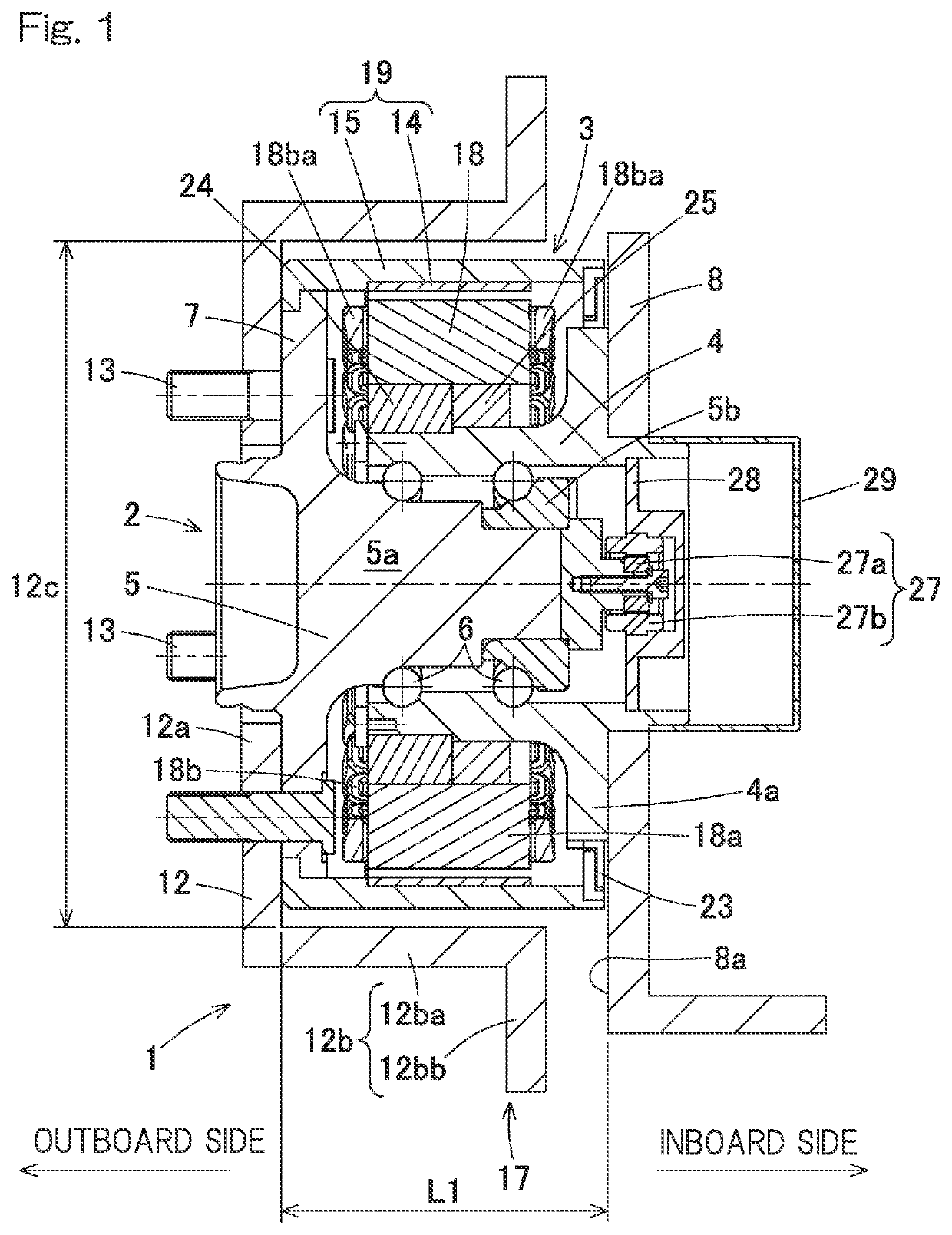
[0066]A vehicle power unit according to an embodiment of the present invention will be described with reference to FIG. 1 to FIG. 4. As shown in FIG. 1, the vehicle power unit 1 includes a wheel bearing 2 and a motor generator 3 that is a generator also serving as a motor.

[0067]Wheel Bearing 2

[0068]The wheel bearing 2 includes an outer ring 4 as a stationary ring, rolling elements 6 arranged in double rows, and an inner ring 5 as a rotary ring. A bearing space between the outer ring 4 and the inner ring 5 is filled with grease. A vehicle mount flange 4a protruding outward in a radial direction is provided on an inboard side part of an outer peripheral surface of the outer ring 4. The vehicle mount flange 4a is fixed to a knuckle 8 that is a chassis frame component. The inner ring 5 includes a hub axle 5a and a partial inner ring 5b fitted to an inboard side part of an outer peripheral surface of the hub axle 5a. The hub axle 5a includes a hub flange 7 at a position protruding with r...


PUM


Abstract

Provided is a motor which includes a stator that can be received in a limited housing space and is capable of providing an increased output without increasing an axial length of the stator; a vehicle power unit including the motor; a generator; as well as a vehicle wheel bearing assembly with the generator. The motor generator includes: a stator including a stator core having an annular shape and stator coils wound around the stator core; and a rotor located opposite to the stator in a radial direction. Each of the stator coils includes coil ends that protrude with respect to an axial width of the stator core in an axial direction. A bus bar is connected to a wiring connection part at the coil ends, and the bus bar is disposed within an axial width of the stator core.

Description

CROSS REFERENCE TO THE RELATED APPLICATION[0001]This application is a continuation application, under 35 U.S.C. § 111(a), of international application No. PCT / JP2019 / 019968, filed May 20, 2019, which is based on and claims Convention priority to Japanese patent application No. 2018-097559, filed May 22, 2018, the entire disclosure of all of which are herein incorporated by reference as a part of this application.BACKGROUND OF THE INVENTIONField of the Invention[0002]The present invention relates to a motor, a vehicle power unit including the motor, a generator, and a vehicle wheel bearing assembly with the generator. The present invention also relates to a technology applied to vehicles.Description of Related Art[0003]As for vehicle motors that are increasing in demand in connection with electric motorization of vehicles, a lot of effort has been made to achieve simplified, space-saving and low-cost wiring connection of motor winding coils. For example, in Patent Document 1 and Pate...

Claims


Application Information

Patent Timeline
Patent Type & Authority Applications(United States)
IPC IPC(8): H02K3/52H02K7/00H02K7/102B60K7/00B60B27/00
CPCH02K3/522H02K7/006H02K7/102B60K7/0007B60T1/065B60B27/0052H02K2203/09B60K2007/0092B60B27/0015H02K7/14Y02T10/72B60L2220/50H02K7/1846H02K9/223B60K2007/0038
Inventor YADA, YUUJINISHIKAWA, KENTAROKAWAMURA, MITSUO
Owner NTN CORP
Why Eureka
Try Eureka