Driving amount controller

a technology of driving amount and controller, which is applied in the direction of adaptive control, electric control, instruments, etc., can solve the problems of reducing slowed down the motor output accordingly, so as to reduce the motor output and reduce the driving amount of the controlled system. , the effect of enhancing the response performan

Active Publication Date: 2008-10-02
HONDA MOTOR CO LTD
View PDF9 Cites 4 Cited by
  • Summary
  • Abstract
  • Description
  • Claims
  • Application Information

AI Technical Summary

Benefits of technology

[0015]Effects of the invention include the following:
[0016]According to the embodiment of the present invention, when the speed variation of the target driving amount for the controlled system is positive, an increase in the motor output attendant on the increase in the speed variation is added to the increase in the motor output due to the increase in the target driving amount. As a result, the motor output at the time of rapid acceleration is enlarged, and the driving amount of the controlled system is also enlarged accordingly. Therefore, it is possible to enhance the response performance in control of the driving amount of the controlled system.
[0017]Further, according to the embodiment of the present invention, when the speed variation of the target driving amount for the controlled system is negative, the decrease in the motor output is restrained according to the decrease (increase in the minus direction) in the speed variation. As a result, the decrease in the motor output is slowed at the time of rapid deceleration, and the decrease in the driving amount of the controlled system is also slowed accordingly. Therefore, it is possible to prevent an erroneous deviation of the driving amount of the controlled system (an overshoot of the actual driving amount relative to the target driving amount for the controlled system).
[0018]Further scope of applicability of the present invention will become apparent from the detailed description given hereinafter. However, it should be understood that the detailed description and specific examples, while indicating preferred embodiments of the invention, are given by way of illustration only, since various changes and modifications within the spirit and scope of the invention will become apparent to those skilled in the art from this detailed description.

Problems solved by technology

As a result, the decrease in the motor output is slowed at the time of rapid deceleration, and the decrease in the driving amount of the controlled system is also slowed accordingly.

Method used


Image

  • Driving amount controller
  • Driving amount controller
  • Driving amount controller

Examples


Embodiment Construction

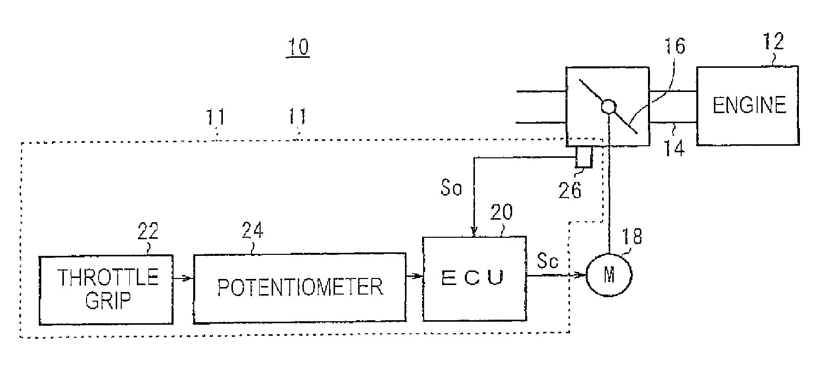
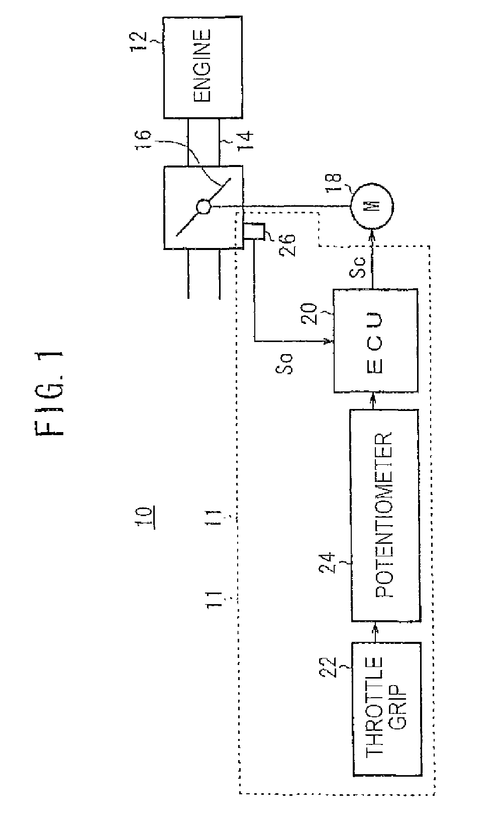
[0034]FIG. 1 shows a functional block diagram of a vehicle 10 on which an engine output controller 11 according to an embodiment of the present invention is mounted. In this embodiment, the vehicle 10 is a motorcycle, and the vehicle 10 has an engine 12. An intake passage 14 connected to the engine 12 is equipped therein with a throttle valve 16 for controlling the quantity of air supplied into the engine 12. The throttle valve 16 is attached to a return spring (not shown), which energized (biases) the throttle valve 16 in the direction for closing the throttle valve 16. In addition, a motor 18 is connected to the throttle valve 16 through a gearing (not shown), whereby the opening of the throttle valve 16 can be regulated. The motor 18 is controlled by an electronic control unit (ECU) 20.

[0035]The opening TH [degrees] of the throttle valve 16 is determined according to the rotation amount ROT [degrees] of a throttle grip 22 provided at a steering handle part of the vehicle 10, and ...


PUM


Abstract

A driving amount controller for reducing a response delay or erroneous deviation in control of a driving amount of a controlled system. The driving amount controller includes an ECU that increases an add-in amount to a duty ratio DUT of a control signal according to an increase in the speed variation ΔDTHR of a target opening DTRH of the throttle valve 16 when the speed variation ΔDTHR is positive. In addition, the ECU increases the add-in amount to the duty ratio DUT of the control signal according to a decrease in the speed variation ΔDTHR when the speed variation ΔDTHR is negative. A throttle valve on a vehicle is an example of the controlled system.

Description

CROSS-REFERENCE TO RELATED APPLICATION[0001]The present application claims priority tinder 35 U.S.C. § 119 to Japanese Patent Application No. 2007-095466, filed Mar. 30, 2007, the entire contents of which are hereby incorporated by reference.BACKGROUND OF THE INVENTION[0002]1. Field of the Invention[0003]The present invention relates to a driving amount controller for controlling a driving amount of a target system (for example, the opening of a throttle valve) by way of the output of a motor.[0004]2. Description of Background Art[0005]The output of an engine in a motorcycle or a four-wheel vehicle is, in general, controlled by use of a throttle grip or an accelerator pedal. More specifically, the output of the engine is determined by regulation according to the turning amount of the throttle grip or the step-in amount of the accelerator pedal.[0006]Ordinarily, a throttle valve is connected to a motor and a return spring, and the regulation of the opening is conducted by a method in...

Claims


Application Information

Patent Timeline
Patent Type & Authority Applications(United States)
IPC IPC(8): F02D45/00
CPCF02D11/105F02D41/045F02D41/107F02D2011/102F02D2041/141F02D2041/1422F02D2041/2027F02D2200/602G05B13/0255
Inventor ASADA, YUKIHIROTSUYUGUCHI, MAKOTOTAKEDA, TORU
Owner HONDA MOTOR CO LTD
Why Eureka
Try Eureka