
Method of manufacturing solar cell module

Inactive Publication Date: 2013-05-16
SANYO ELECTRIC CO LTD
View PDF2 Cites 3 Cited by
  • Summary
  • Abstract
  • Description
  • Claims
  • Application Information

AI Technical Summary

Benefits of technology

This patent aims to improve the connection strength of interconnection tabs without needing additional work such as additional soldering. The invention achieves this by keeping the solder layer of the rear-side interconnection tab unwelded at the area where it is connected to the front-side interconnection tab. This results in a sufficient amount of solder between the tabs, enhancing the connection strength and reliability.

Problems solved by technology

For this reason, there is a possibility that the interconnection tabs have only a small amount of solder therebetween in the latter connection step, which might lower the connection strength of the interconnection tabs.
When the interconnection tabs having no solder on the front surfaces are used, the connect strength of the interconnection tabs might decrease, which requires additional work such as additional soldering.

Method used


Image

  • Method of manufacturing solar cell module
  • Method of manufacturing solar cell module
  • Method of manufacturing solar cell module

Examples


Embodiment Construction

[0034]An embodiment of the invention is described in detail with reference to the drawings. Note that the same or corresponding parts are given the same reference numerals throughout the drawings, and are not described again to avoid repetitive descriptions.

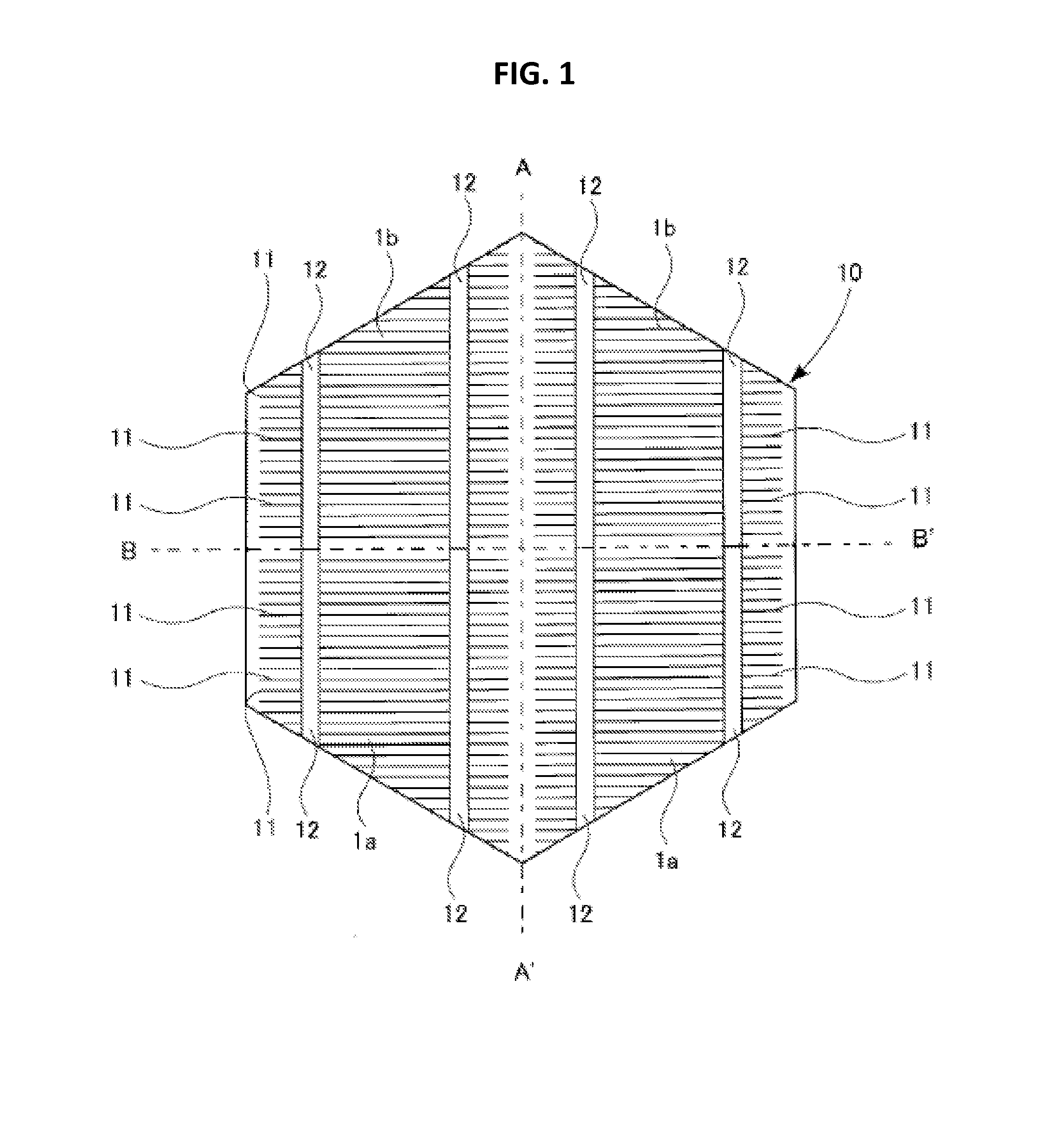
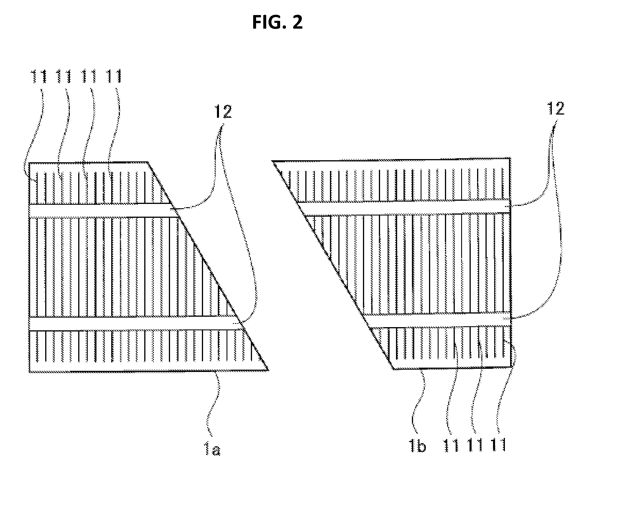
[0035]FIG. 1 shows the configuration of a solar cell substrate 10 which has not been divided into four solar cells yet, and FIGS. 2 and 3 show arranged two solar cells 1a and 1b, out of the divided four solar cells. As shown in the drawings, solar cell substrate 10 is shaped as a substantially-regular hexagon in a plan view. Finger electrodes 11 and bus bar electrodes 12 are formed on the front surface of solar cell substrate 10, and finger electrodes 13 and bus bar electrodes 14 are formed on the rear surface of solar cell substrate 10.

[0036]Solar cell substrate 10 is formed, for example, with an n-type region and a p-type region inside thereof such that a joint portion configured to generate an electric field for carrier separa...


PUM


Abstract

A method of manufacturing a solar cell module includes a step of connecting electrodes of solar cells with an interconnection tab so as to form a first solar cell unit, by welding the interconnection tab to the electrodes while remaining an unmelted part of solder of the interconnection tab, and a step of connecting an interconnection tab of a second solar cell unit to the interconnection tab of the first solar cell unit at the unmelted part of the interconnection tab of the first solar cell unit.

Description

CROSS REFERENCE TO RELATED APPLICATIONS[0001]This application is a continuation application of International Application No. PCT / JP2011 / 0062376, filed on May 30, 2011, entitled “METHOD OF MANUFACTURING SOLAR CELL MODULE”, which claims priority based on Article 8 of Patent Cooperation Treaty from prior Japanese Patent Applications No. 2010-124427, filed on May 31, 2010, the entire contents of which are incorporated herein by reference.BACKGROUND OF THE INVENTION[0002]1. Field of the Invention[0003]This disclosure relates to a method of manufacturing a solar cell module.[0004]2. Description of Related Art[0005]A solar cell system uses a solar cell module including several tens of solar cells as power sources arranged on a flat plane in order to protect the solar cells from external damage and to facilitate the handling of them.[0006]Document 1 (Japanese Patent Application Publication No. 2007-235113) has recently proposed a solar cell module which enhances the charging rate of the sol...

Claims


Application Information

Patent Timeline
IPC IPC(8): H01L31/18
CPCH01L31/0508H01L31/18Y02E10/50H01L31/0512
Inventor KAWASHITA, YOSHIHIDE
Owner SANYO ELECTRIC CO LTD
Features
  • Generate Ideas
  • Intellectual Property
  • Life Sciences
  • Materials
  • Tech Scout
  • Unparalleled Data Quality
  • Higher Quality Content
  • 60% Fewer Hallucinations
Learn More