Secure data storage in raid memory devices

a memory device and data storage technology, applied in the direction of memory adressing/allocation/relocation, instruments, error detection/correction, etc., can solve the problems of high cost of calculation, bottleneck, and inability to optimize, so as to reduce overhead

Active Publication Date: 2013-05-16
EMC IP HLDG CO LLC
View PDF6 Cites 259 Cited by
  • Summary
  • Abstract
  • Description
  • Claims
  • Application Information

AI Technical Summary

Benefits of technology

[0036]The present embodiments seek to reduce the overheads while retaining the utilization advantages of the RAID 6 schemes mentioned above. Th

Problems solved by technology

One solution is to use the Reed Solomon error correction code, which is expensive to calculate.
Again, if all the parity bits are on the same two disks then the bottleneck becomes a problem.
In terms of computation, however, it is not optimal.
That is to say, a particularly high update overhead is encountered when updating the kth diagonal (the one that has no corresponding row) since it is spread over all the oth

Method used


Image

  • Secure data storage in raid memory devices
  • Secure data storage in raid memory devices
  • Secure data storage in raid memory devices

Examples


first embodiment

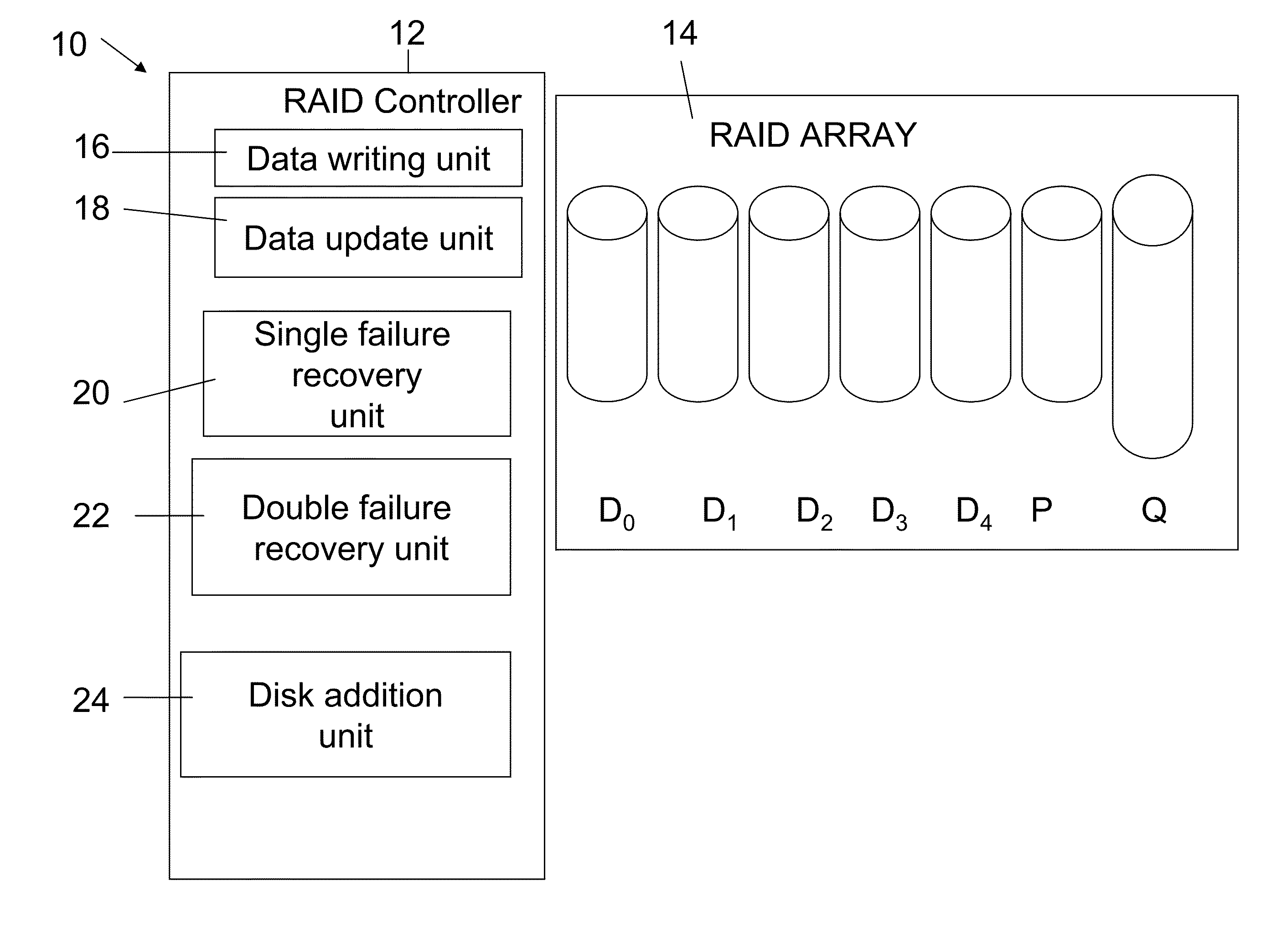
[0083]Reference is now made to FIG. 4, which illustrates a redundant array of independent disk (RAID) memory storage system 10 according to the present invention. The memory storage system 10 comprises a controller 12 and an array 14 of data storage disks, in this example five data disks D0 . . . D4.

[0084]The controller 12 includes a data write unit 16 for writing initial data into the array, an update unit 18 for updating existing data in the array, a single failure recovery unit 20 for recovering data after a single disk failure and a double failure recovery unit 22 for recovering data following concurrent failure of two disks. A disk addition unit 24 manages the addition of a new disk to the system, either after failure of an existing disk or when it is desired to expand the system 10. The operation of each of these units is discussed in greater detail herein below.

[0085]Each of the disks in the array 14 stores a column of data blocks. The same data block in successive disks form...

second embodiment

[0121]Reference is now made to FIG. 11, which is a simplified diagram illustrating the present invention. Again K is set at 5, and there are 5 columns D0-D4. There are four rows in the five disks and four rows in the parity disk. However the Q disk also has four rows, since one of the diagonals is left blank.

[0122]As illustrated in FIGS. 11 and 12, an equivalent way of providing the effect is by setting one of the diagonals as a virtual diagonal, whose content is fixed and equals zero. In fact any number of diagonals may be set as virtual. It is merely a matter of efficient mapping between cells in the stripe and physical disk locations to eliminate any further capacity overhead. The only constraint when performing such mappings is that cells in the same column must reside on the same disk, and vice versa.

[0123]FIGS. 13, 14 and 15 illustrate various distributions of the P and Q data amongst the actual disks of a system, in accordance with this second embodiment. The disks comprise s...


PUM


Abstract

A redundant array of independent disk (RAID) memory storage system comprising data storage blocks arranged in a first plurality of data rows and a second plurality of data columns, wherein parity data is stored in additionally defined parity blocks, and wherein numbers of data blocks in respective columns are different, to accommodate the additional diagonal parity data block that the geometry of the system requires. The system is suitable for an SSD array in which sequential disk readout is not required.

Description

FIELD AND BACKGROUND OF THE INVENTION[0001]The present invention, in some embodiments thereof, relates to a method and apparatus for secure data storage in RAID memory devices and, more particularly, but not exclusively, to such a method and apparatus which conforms to the requirements of the RAID 6 specification for data recovery following two disk failures.[0002]Raid is an acronym for Redundant Array of Independent Disks, and is a system for storing data on multiple disks in which redundancy of data storage between the disks ensures recovery of the data in the event of failure. This is achieved by combining multiple disk drive components into a logical unit, where data is distributed across the drives in one of several ways called RAID levels.[0003]RAID is now used as an umbrella term for computer data storage schemes that can divide and replicate data among multiple physical disk drives. The terms disks and drives will be used interchangeably henceforth. The physical disks are sa...

Claims


Application Information

Patent Timeline
IPC IPC(8): G06F12/16G06F12/02
CPCG06F11/1092G06F2211/1057G06F11/1008G06F11/1076
Inventor HALLAK, RENENSEGEV, YARON
Owner EMC IP HLDG CO LLC
Why Eureka
Try Eureka