Gas turbine engine lockout reduction

a gas turbine engine and lockout reduction technology, applied in the direction of engines, machines/engines, engine components, etc., can solve the problems of reducing power gradually, reducing power, and causing the upper portion of the rotor to heat up and expand more than the lower portion, so as to reduce the lockout period, reduce the lockout time of the gas turbine engine, and reduce the power output level

Active Publication Date: 2013-05-23
GENERAL ELECTRIC CO
View PDF4 Cites 5 Cited by
  • Summary
  • Abstract
  • Description
  • Claims
  • Application Information

AI Technical Summary

Benefits of technology

[0007]This need is addressed by the present invention, which according to one aspect provides methods for heating the casing and / or cooling the rotor of a gas turbine engine in order to reduce the lockout period.
[0008]According to one aspect of the invention, a method is provided of reducing lockout time of a gas turbine engine which includes, in serial flow communication: an inlet, a compressor, a combustor, a turbine, and an exhaust duct, where the compressor and the turbine are carried on a turbomachinery rotor and each include an array of blades mounted for rotation inside a casing of the engine. The method includes: operating the engine at a first power output level; shutting down operation of the engine without substantially reducing the power output level beforehand, wherein thermomechanical changes occur in the rotor and the casing subsequent to the shutdown that tend to reduce a radial clearance between at least one of the blades and the casing; and subsequent to shutting down the engine, heating the casing of the engine so as to expand the casing and increase a radial clearance between the blades of the rotor and the casing.

Problems solved by technology

As a result the blade clearances tend to open or close during changes in engine power output.
However, operational reasons can require that the external load be removed and that the engine be shut down immediately, without being able to gradually reduce power.
Also, once the engine stops rotating natural convection patterns cause the upper portions of the rotor to heat up and expand more than the lower portions.
This causes bending or bowing of the rotor that further reduces radial clearances at specific locations.
This period is undesirable for a number of reasons including the cost and physical inconvenience of not having the engine in service.

Method used


Image

  • Gas turbine engine lockout reduction
  • Gas turbine engine lockout reduction
  • Gas turbine engine lockout reduction

Examples


Embodiment Construction

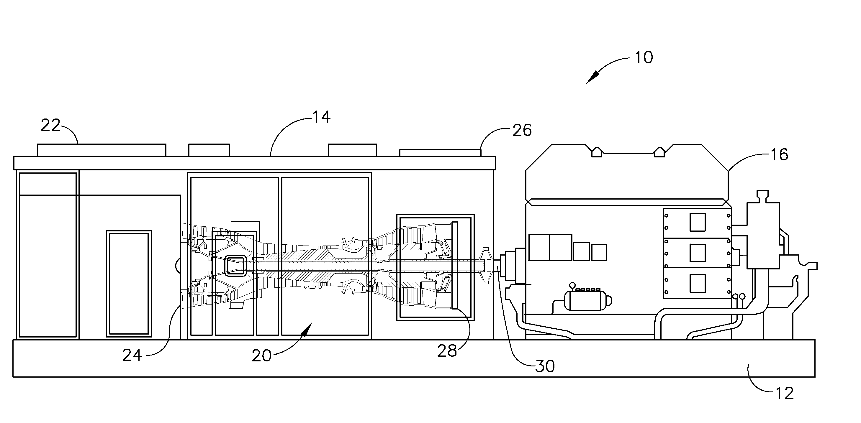
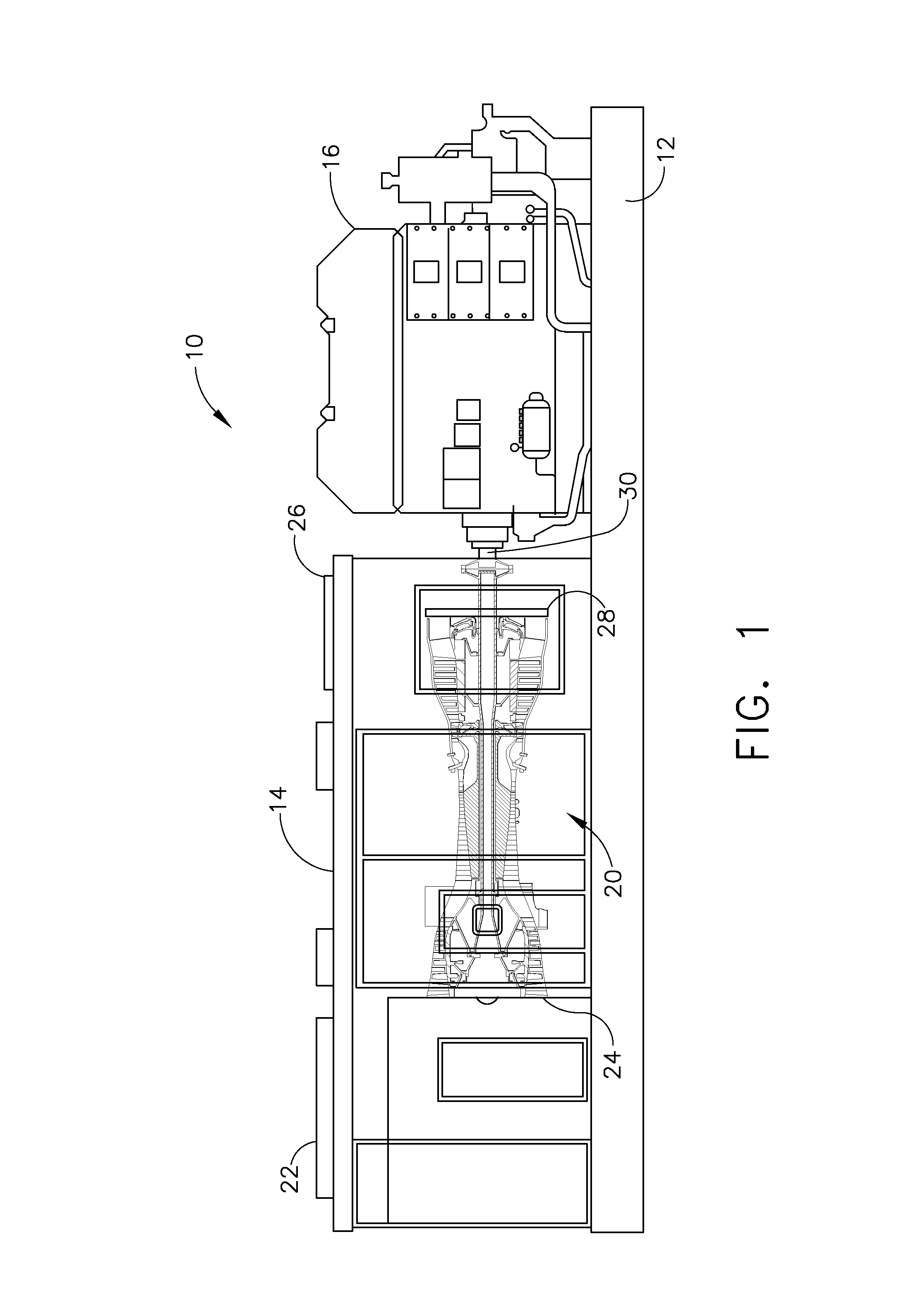
[0016]Referring to the drawings wherein identical reference numerals denote the same elements throughout the various views, FIG. 1 depicts a genset module 10. It includes a base 12 upon which are mounted an engine enclosure 14 and an electrical generator 16. The electrical generator 16 is used as a representative example of an external load device. A gas turbine engine 20 (or simply “engine”) is disposed inside the engine enclosure 14. The engine enclosure 14 includes a combustion air inlet 22 coupled in flow communication with an inlet 24 of the engine 20, and an exhaust gas exit 26 coupled in flow communication with an exhaust duct 28 of the engine 20. The gas turbine engine 20 is coupled by an output shaft 30 to the electrical generator 16.

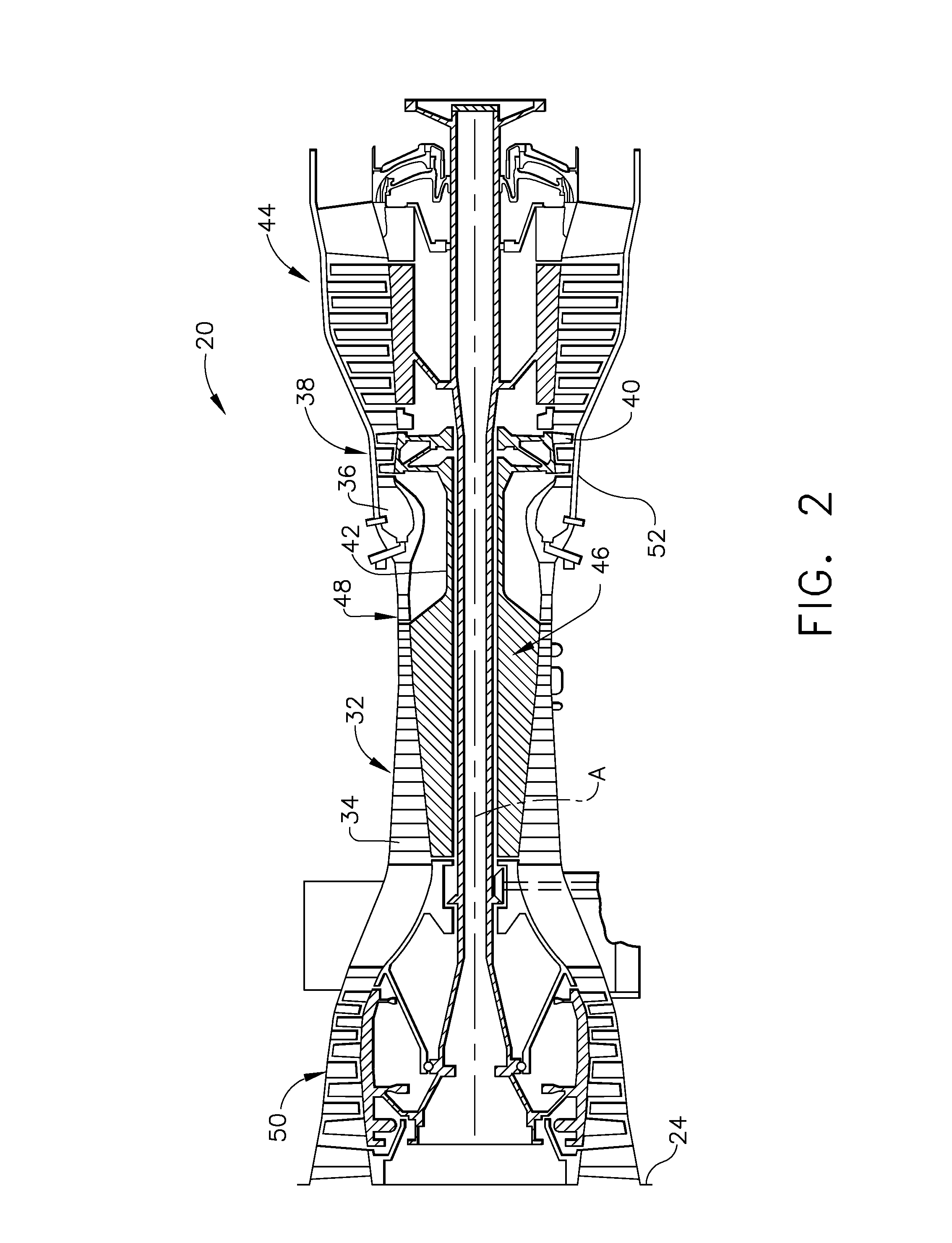
[0017]Referring to FIG. 2, the engine 20 includes a high pressure compressor (“HPC”) 32 carrying a number of stages of rotating compressor blades 34, a combustor 36, and a high pressure turbine (“HPT”) 38 carrying a number of stages of rotating...


PUM


Abstract

A method is provided of reducing lockout time of a gas turbine engine which includes: an inlet, a compressor, a combustor, a turbine, and an exhaust duct, where the compressor and the turbine are carried on a turbomachinery rotor and each include an array of blades mounted for rotation inside a casing of the engine. The method includes: operating the engine at a first power output; shutting down operation of the engine without substantially reducing the power output beforehand, wherein thermomechanical changes occur in the engine subsequent to shutdown that tend to reduce a radial clearance between at least one of the blades and the casing; and subsequent to shutting down the engine, (1) heating the casing and/or (2) pumping an airflow of ambient air into the inlet and through the casing, past the rotor, and out the exhaust duct, so as to reverse at least partially the thermomechanical changes.

Description

BACKGROUND OF THE INVENTION[0001]This invention relates generally to gas turbine engines and more particularly to methods for operating such engines during a shutdown period.[0002]A gas turbine engine includes a turbomachinery core having a high pressure compressor, a combustor, and a high pressure or gas generator turbine in serial flow relationship. The core is operable in a known manner to generate a primary gas flow. In a turboshaft engine, another turbine disposed downstream of the core (referred to as a low pressure, “work”, or “power” turbine) extracts energy from the primary flow to drive a shaft or other mechanical load. One common use is to couple the gas turbine engine to an external load such as a pump, compressor, or electrical generator.[0003]For efficient operation, the turbomachinery in a gas turbine engine depends on maintaining small but definite radial clearances between the tips of the rotating blades and the stationary annular casing that surrounds them. The cas...

Claims


Application Information

Patent Timeline
Patent Type & Authority Applications(United States)
IPC IPC(8): F02C1/00
CPCF01D25/34F01D25/08F01D11/24F01D21/00Y02T50/60
Inventor SHIROONI, STEVEALI, MOHAMED AHMEDBRANDS, MARKALTMAN, JOHN EDWARDSHAMIM, ABDUS
Owner GENERAL ELECTRIC CO
Why Eureka
Try Eureka