Electrode-Supporting Assembly for Contact-Start Plasma Arc Torch

a technology of electrode support and contact-start plasma, which is applied in the field of contact-start plasma torches, can solve the problems of increasing the cost of electrodes, reducing contact, and reducing the size of contact, and achieves the effect of reducing cost and small siz

Active Publication Date: 2013-05-23
THERMACUT KS
View PDF11 Cites 52 Cited by
  • Summary
  • Abstract
  • Description
  • Claims
  • Application Information

AI Technical Summary

Benefits of technology

[0027]In some embodiments, a conductive stranded element such as a twisted or braided wire or cable (which is at least partially non-resilient) is connected between the contact element and the plunger to pass at least part of the current. In such cases, proper sizing of the resilient element and the conductive stranded element can assure sufficient current to the electrode for operation in both its positions, while allowing sufficient resiliency in the resilient element to assure the smooth transfer between the two limit positions of the electrode when operating the torch. In these cases, the means to maintain a consistent rear position of the electrode can be provided in a variety of ways. In one scheme, the means to maintain a consistent rear position of the electrode is provided by having the resilient element be a compression spring that is sized, relative to the other elements, such that movement of the electrode to its rear position causes the plunger to compress the coils of the resilient element until the coils of the spring are in abutting contact. This stacked configuration of the spring serves as a rigidly non-compressible cylinder for limiting the rearward motion of the electrode. In an alternative embodiment, where the conductive

Problems solved by technology

Additionally, the contact between the plunger and the electrode is provided only across relatively small planar contact surfaces, which may be susceptible to reduced contact due to any unwanted material interposed between these surfaces.
Unless the electrode includes the spring, the spring may be lost when the torch is opened to change the electrode.
Securing the conductive element and spring to the electrode requires that these components be replaced with the electrode, increasing expense of the electrode,

Method used


Image

  • Electrode-Supporting Assembly for Contact-Start Plasma Arc Torch
  • Electrode-Supporting Assembly for Contact-Start Plasma Arc Torch
  • Electrode-Supporting Assembly for Contact-Start Plasma Arc Torch

Examples


Embodiment Construction

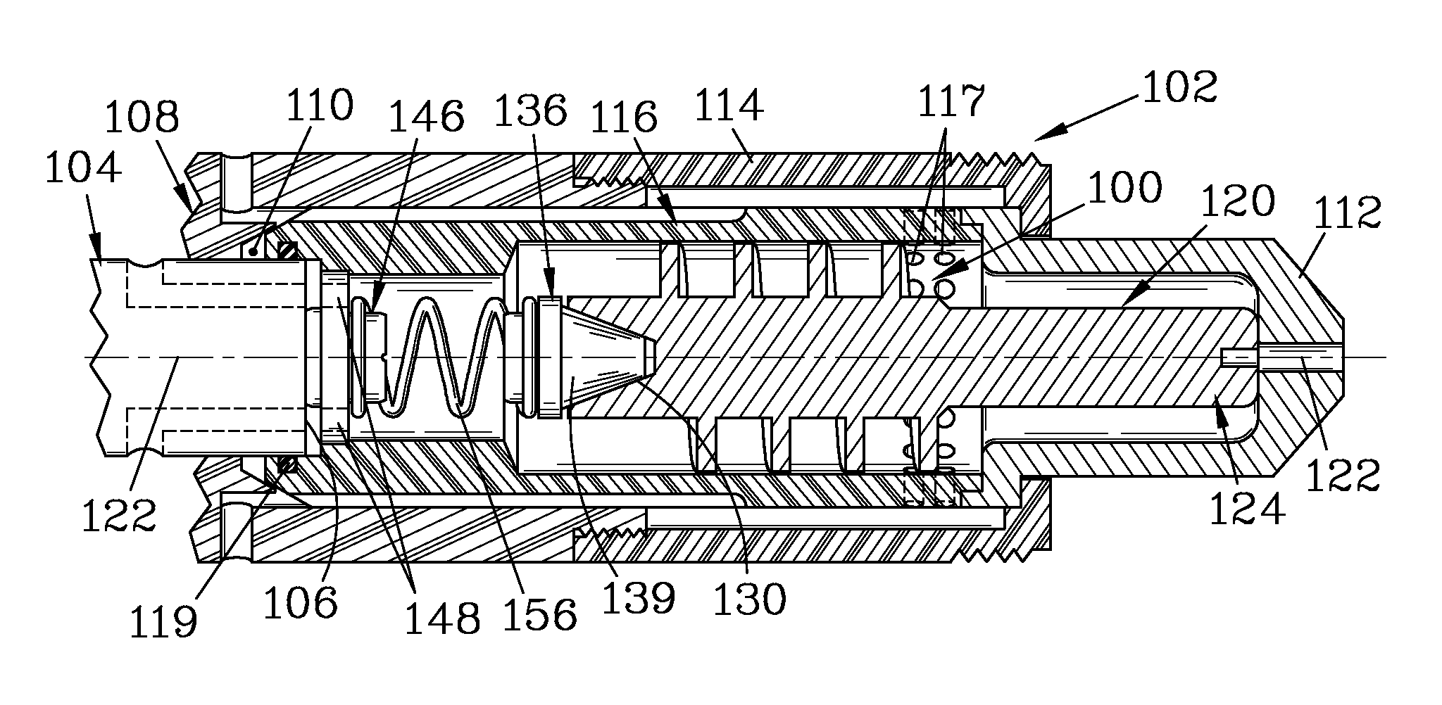
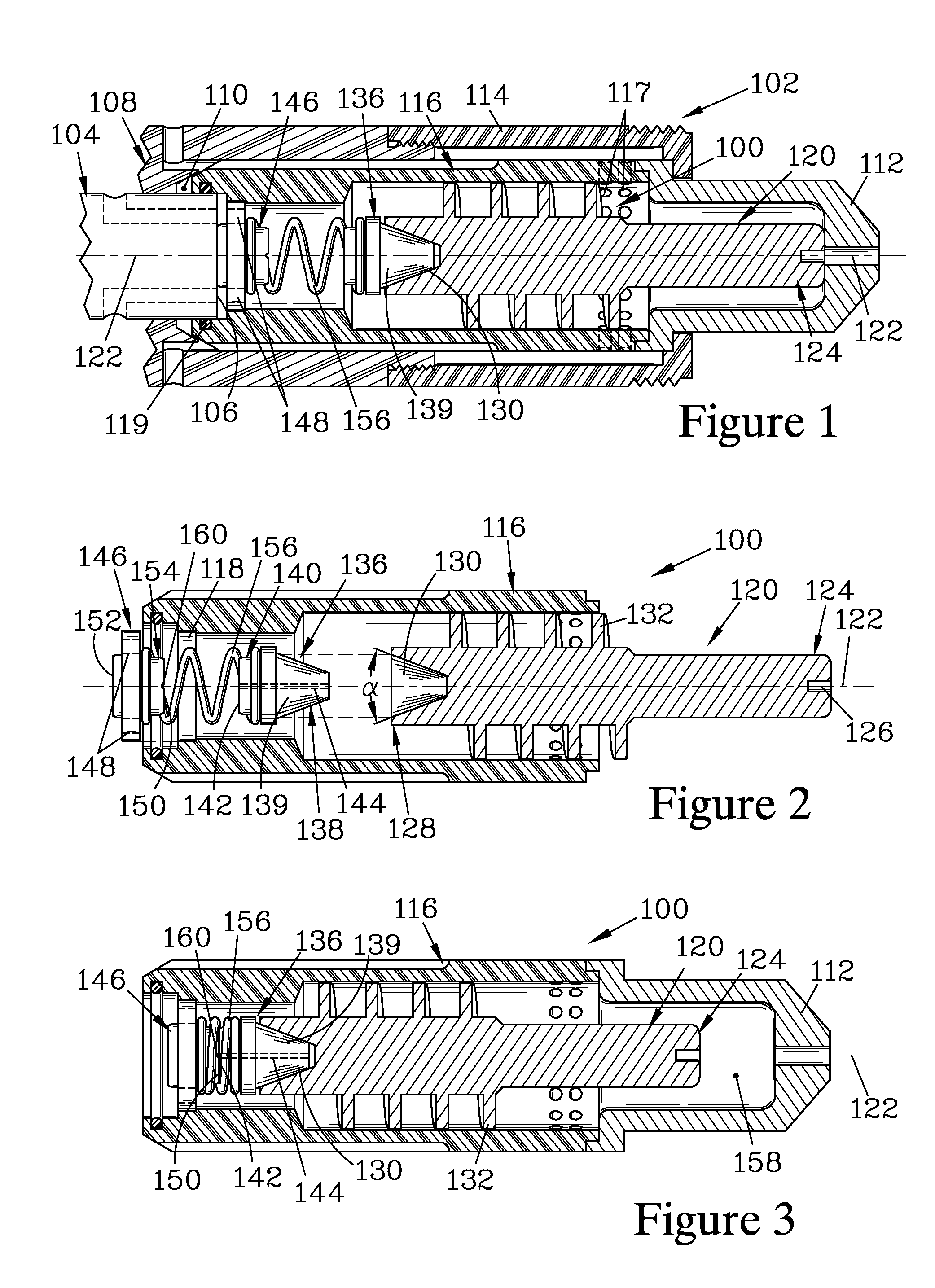
[0044]FIGS. 1 through 3 are section views illustrating an electrode-supporting assembly 100 for use in a contact start plasma arc torch 102 (only partially shown). The torch 102 can be similar to those torches taught in U.S. Pat. Nos. 8,035,055 and 8,115,136 with the electrode-supporting assembly 100 replacing the conventional structure for supporting and providing electrical current to an electrode. The torch 102 has a current-carrying cathode 104 (shown in FIG. 1) that connects to a power supply (not shown) and has a power transfer surface 106 for contacting a conventional electrode. The cathode 104 is mounted in a torch body element 108 that is configured with a torch recess 110 for receiving a conventional insulated swirl ring element. A nozzle element 112 can be secured onto the insulator and the torch body element 108 by a retaining element 114 that threadably engages the torch body element 108.

[0045]The assembly 100 has an insulator 116 that is configured to be slidably insta...


PUM

PropertyMeasurementUnit
Diameteraaaaaaaaaa
Lengthaaaaaaaaaa
Electrical conductoraaaaaaaaaa

Abstract

An electrode-supporting assembly for a contact-start plasma arc torch has an insulator that partially houses an electrode, and employs a spring-loaded plunger to bias the electrode to a forward position. The spring is engaged between the plunger and a contact element attached to the insulator, and may conduct electrical current to the electrode. The plunger, spring, and contact element are retained in the insulator when the torch is opened to replace the electrode, which is a consumable part. The electrode and the plunger have axially-engagable mating surfaces to assure good thermal and electrical conductivity therebetween. Conductivity can be further enhanced by forming the plunger of silver or a silver-bearing alloy. In some embodiments, a passage through the insulator is partitioned into forward and rear chambers, with the plunger, spring, and contact element trapped in the rear chamber.

Description

FIELD OF THE INVENTION[0001]The present invention relates to contact-start plasma torches, and more particularly to a novel structure for providing electrical connection of a consumable electrode with a power supply.BACKGROUND OF THE INVENTION[0002]U.S. Pat. No. 4,791,268 teaches a contact-start plasma arc torch where the electrode is biased forward by a plunger which resides in an enclosed structure; this structure is formed such that a significant portion of the electrode is not exposed to gas flow which would enhance cooling, and there appears to be little gas flow past the plunger. Additionally, the contact between the plunger and the electrode is provided only across relatively small planar contact surfaces, which may be susceptible to reduced contact due to any unwanted material interposed between these surfaces.[0003]U.S. Pat. Nos. 8,035,055 and 8,115,136 teach a variety of electrode configurations for contact-start plasma arc torches, as well as teaching a prior art electrod...

Claims


Application Information

Patent Timeline
IPC IPC(8): B23K10/00
CPCB23K10/00H05H2001/3489H05H1/34H05H1/3489H05H1/3423H05H1/3478H05H1/38
Inventor CROWE, GEORGE A.
Owner THERMACUT KS
Why Eureka
Try Eureka