
Integrated circuit including a differential power amplifier with a single ended output and an integrated balun

a technology of integrated circuit and power amplifier, which is applied in the direction of amplifiers, high-frequency amplifiers, electric devices, etc., can solve the problems of converter waste valuable space use of balun converter on the integrated circuit die,

Inactive Publication Date: 2013-05-23
DSP GROUP
View PDF8 Cites 2 Cited by
  • Summary
  • Abstract
  • Description
  • Claims
  • Application Information

AI Technical Summary

Benefits of technology

This patent describes a differential power amplifier integrated circuit that has a single ended output. The output is converted using a BALUN converter that includes capacitors and inductors. The inductors are made up of the inherent inductance of the bond wires that connect the integrated circuit die to external elements. The length and thickness of the wires can be controlled by changing their length, thickness, or position in relation to the pads and pins. The position of the pads and pins can also be adjusted to optimize the inductance. The invention also includes a method for converting the output of the differential power amplifier to a single ended output. The technical effect of this invention is to provide a more efficient and reliable way to output signals from an integrated circuit.

Problems solved by technology

One drawback is that differential amplifiers produce two output signals which have a phase shift between them so that they cannot be directly combined to form a single ended output without first bringing the two output signals into alignment.
Use of a BALUN converter on the die of the integrated circuit would waste valuable space.
In either case the converter wastes valuable space on the die of the integrated circuit unless the integrated circuit does not combine the outputs of the differential amplifier and leaves it to elements external to the integrated circuit to combine the signals.

Method used


Image

  • Integrated circuit including a differential power amplifier with a single ended output and an integrated balun
  • Integrated circuit including a differential power amplifier with a single ended output and an integrated balun
  • Integrated circuit including a differential power amplifier with a single ended output and an integrated balun

Examples


Embodiment Construction

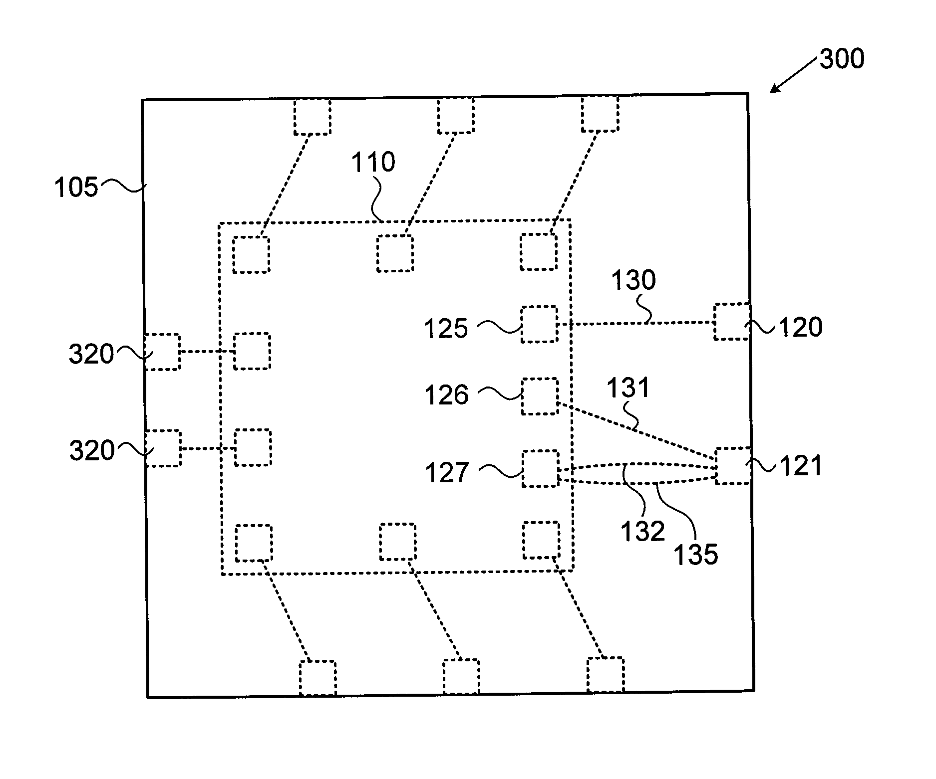
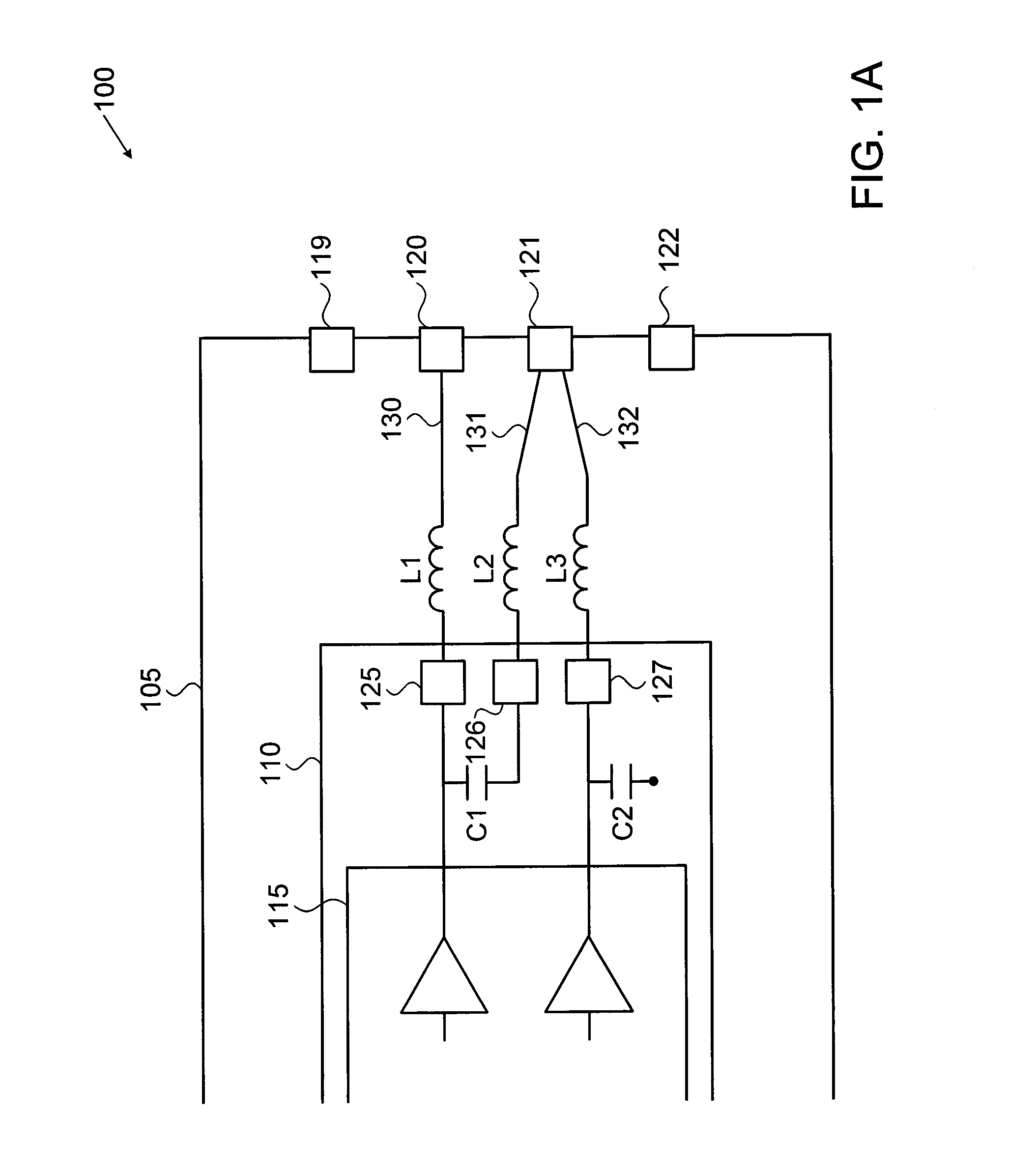
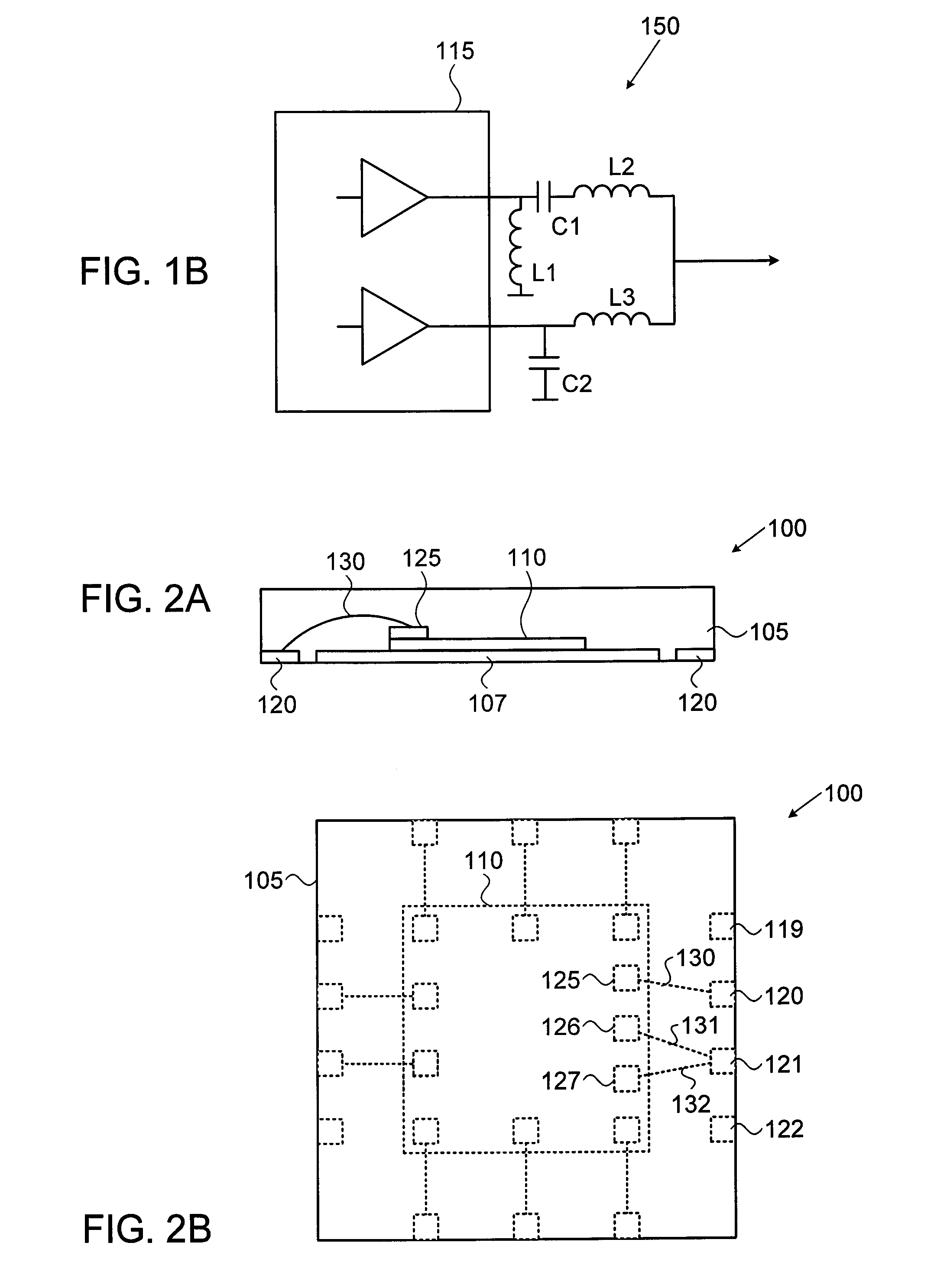
[0025]FIG. 1A is a schematic illustration of an integrated circuit 100 with a differential amplifier 115, and FIG. 1B is a schematic illustration of the electronic circuit layout of an integrated BALUN 150 as implemented by FIG. 1A, according to an exemplary embodiment of the invention. As shown in FIG. 1A integrated circuit 100 includes a die 110 with an electronic circuit embedded therein, the die including a differential amplifier 115. Optionally, integrated circuit 100 is placed on a metallic paddle 107 (shown in FIG. 2A) and encased by an integrated circuit (IC) package 105 (e.g. molded from plastic). In an exemplary embodiment of the invention, die 110 includes pads (e.g. 125, 126 and 127), which are positioned on the edges of die 110 to electrically connect between die 110 and contact pins (e.g. 120, 121 and 122) located on the bottom of IC package 105 for connecting the integrated circuit to external elements. Optionally, the contact pins (e.g. 120, 121 and 122) are original...


PUM


Abstract

An integrated circuit, including, a die with an electronic circuit embedded thereon; wherein the electronic circuit includes a differential power amplifier and pads to electronically interface with the electronic circuit; a packaging encasing the die with contact pins to connect between the integrated circuit and external elements; wires connecting between the pads and the contact pins; a converter that includes capacitors and inductors to combine the outputs from the differential power amplifier to form a single ended output at one of the contact pins; wherein inherent inductance of some of the wires serve as the inductors of the converter.

Description

FIELD OF THE INVENTION[0001]The present invention relates generally to an integrated circuit including a differential power amplifier with a single ended output embedded therein and more specifically wherein the integrated circuit package includes an integrated BALUN to provide the single ended output.BACKGROUND OF THE INVENTION[0002]Many integrated circuit designers use differential amplifiers to improve the amplification quality in integrated circuits. The differential amplifiers allow stronger amplification without adding unnecessary noise to the integrated circuit.[0003]One drawback is that differential amplifiers produce two output signals which have a phase shift between them so that they cannot be directly combined to form a single ended output without first bringing the two output signals into alignment. The alignment of the output signals requires use of a converter that converts balanced input to unbalanced output or vice versa, and is generally referred to as a BALUN. Use...

Claims


Application Information

Patent Timeline
Patent Type & Authority Applications(United States)
IPC IPC(8): H01L23/50H01L23/00
CPCH03F1/565H03F3/189H01L23/50H01L24/85H01L2224/85H01L2924/30107H01L2224/49113H01L2224/48091H01L2924/00014H01L2924/00H01L2224/05554H01L2924/14H01L2924/181H01L24/49H01L24/48H01L2224/45099H01L2224/05599H01L2924/00012
Inventor GENIK, ANATOLYMOSTOV, ALEX
Owner DSP GROUP
Learn More