Antenna, radio receiver and method for manufacturing antenna

Active Publication Date: 2013-05-23
CASIO COMPUTER CO LTD
View PDF2 Cites 0 Cited by
  • Summary
  • Abstract
  • Description
  • Claims
  • Application Information

AI Technical Summary

Benefits of technology

The present invention provides an easy-to-manufacture antenna that is highly sensitive to radio waves even in the presence of metal. This invention also provides a radio receiver that includes the antenna and a method for manufacturing the antenna. Specifically, the patent describes a method of manufacturing an antenna by forming a magnetic core and winding a wire around it to create a coil. A secondary magnetic path member is then added that is disposed near the core with a spacer in between to prevent magnetic coupling. The technical effect of this invention is to provide an improved antenna for radio receivers that is easy to manufacture and has excellent sensitivity to radio waves even when a metal member is nearby.

Problems solved by technology

In this case, namely, in the case where a metal member is used in a radio receiver, if an antenna is disposed near the metal member, the so-called eddy current is induced, and loss is caused thereby, which leads to decrease of sensitivity of the antenna to standard radio waves.

Method used


Image

  • Antenna, radio receiver and method for manufacturing antenna
  • Antenna, radio receiver and method for manufacturing antenna
  • Antenna, radio receiver and method for manufacturing antenna

Examples


first embodiment

[0030]An antenna and a radio receiver including the antenna in accordance with a first embodiment of the present invention are described referring to FIGS. 1 to 9.

[0031]In the embodiment, a radio controlled watch in which an antenna is installed is described as a radio receiver.

[0032]The present invention is not limited to the following embodiments or the accompanying drawings.

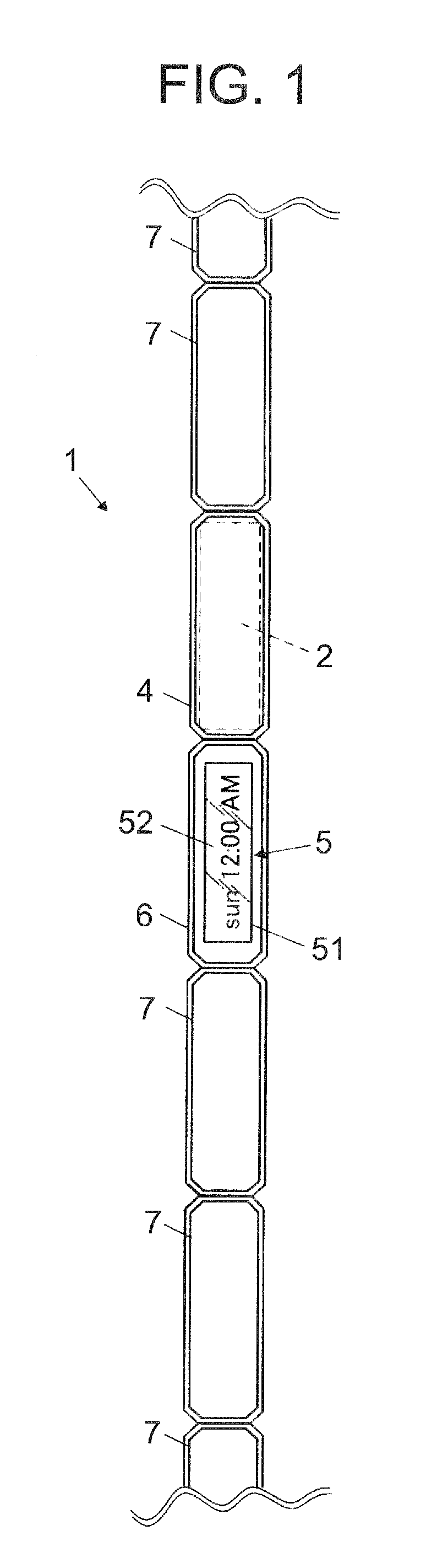
[0033]FIG. 1 is a front view of a radio controlled watch (radio receiver) in accordance with the first embodiment.

[0034]As shown in FIG. 1, a radio controlled watch 1 includes an antenna 2 and an antenna case 4 in which the antenna 2 is housed.

[0035]In the embodiment, the radio controlled watch 1 also includes a watch main body 5, a watch case 6, and band pieces 7. A display device 51, electronic components (not shown) including a receiving circuit to receive radio waves with the antenna 2, and the like are installed in the watch main body 5. The display device 51 displays time or the like. The watch main body...

second embodiment

[0137]Next, an antenna, a radio receiver including the antenna, and a method for manufacturing the antenna in accordance with a second embodiment of the present invention are described referring to FIGS. 10 to 12.

[0138]In the second embodiment, only the configuration of a secondary magnetic path member is different from that in the first embodiment. Hence, in the following, points different from the first embodiment are described mainly.

[0139]FIG. 10 is a plan view of an antenna 8 in accordance with the second embodiment.

[0140]FIG. 11 is an elevation view of the antenna 8 viewed from the arrow XI of FIG. 10.

[0141]FIG. 12 is a cross-sectional view of the antenna 8 taken along the line XII-XII of FIG. 10.

[0142]A radio receiver in the second embodiment is, like the first embodiment, a radio controlled watch including the antenna 8 and the antenna case 4 which is made of a metal material and in which the antenna 8 is housed. The radio controlled watch corrects a current time on the basi...


PUM

PropertyMeasurementUnit
Magnetismaaaaaaaaaa

Abstract

An antenna includes an elongated magnetic core, a secondary magnetic path member, a spacer and a coil. The secondary magnetic path member is disposed near the core, and forms a secondary magnetic path. The spacer is disposed between the core and the secondary magnetic path member so as to prevent the core and the secondary magnetic path member from being magnetically coupled. The coil is formed by winding a wire around the core in such a way as to bundle the core and the secondary magnetic path member together.

Description

BACKGROUND OF THE INVENTION[0001]1. Field of the Invention[0002]The present invention relates to an antenna, a radio receiver, and a method for manufacturing the antenna.[0003]2. Description of the Related Art[0004]Conventionally, there is known a radio receiver, such as a radio controlled timepiece, including an antenna which receives standard radio waves including time information. The radio receiver automatically corrects a current time on the basis of the time information.[0005]As the antenna, which receives standard radio waves, of a radio controlled timepiece as an example of a radio receiver, there is an antenna often used, the antenna being constituted of a core made of a magnetic material sensitive to radio waves, such as an amorphous metal or ferrite, and a coil winding around the core.[0006]In a case where a radio receiver is a radio controlled watch, in order to, for example, make the radio controlled watch sumptuous or improve design or durability of the radio controlle...

Claims


Application Information

Patent Timeline
IPC IPC(8): H01Q7/08
CPCY10T29/49016H01Q7/08
Inventor SOMEYA, KAORU
Owner CASIO COMPUTER CO LTD
Why Eureka
Try Eureka