Backlight Module and LCD Device

a backlight module and lcd technology, applied in the field of backlight modules, can solve the problems of high cost, present non-uniform luminance and color, large etc., and achieve the effects of simplifying the heat dissipation path, reducing the frame width of the backlight module, and improving heat dissipation efficiency

Inactive Publication Date: 2013-05-23
TCL CHINA STAR OPTOELECTRONICS TECH CO LTD
View PDF8 Cites 14 Cited by
  • Summary
  • Abstract
  • Description
  • Claims
  • Application Information

AI Technical Summary

Benefits of technology

[0008]In order to overcome the problems that the prior art backlight modules have a wide frame and poor heat dissipation efficiency, an objective of the present disclosure is to provide a backlight module that has a narrow frame and can dissipate heat easily.
[0025]The present disclosure has the following benefits: as compared to the prior art, the backlight module and the LCD device of the present disclosure have the thicknesses of a plurality of elements including the point light source and the PCB superposed on each other in a direction parallel to or inclined with respect to a side surface of the light guide plate to reduce the frame width of the backlight module. Furthermore, this can simplify the heat dissipation path of heat generated by the point light source, improve the heat dissipation efficiency and prevent accidental collisions between the light guide plate and the point light source. Therefore, the backlight module and the LCD device of the present disclosure feature a narrow frame and can dissipate heat easily.

Problems solved by technology

Backlight modules of the direct-lit type feature a simple structure, high luminance, a desirable heat dissipation effect and a small frame, but have the main shortcomings that they require use of a large number of LEDs, have a high cost and tend to present non-uniform luminance and colors and, moreover, make the whole backlight module thick and bulky.
Firstly, because the LEDs are disposed at the side edge of the light guide plate, collisions between the LEDs and the light guide plate occur easily. Particularly when the backlight module is handled or impacted, accidental collisions between the LEDs and the light guide plate may cause damage to the LEDs.
Secondly, the thicknesses of the LEDs, the PCB and the aluminum extruded piece add to each other at the side edge of the light guide plate in a direction perpendicular to a side surface of the light guide plate, which makes the whole thickness of the backlight module of the edge-lit type relatively large. Consequently, a wide frame must be used to accommodate the increased thickness, and this is in contradiction to the development tendency towards a narrow frame.
Thirdly, heat generated by the LEDs during operation must be timely dissipated outwards. The heat dissipation path for the LEDs passes through the PCB, a side edge of the aluminum extruded piece and a bottom surface of the aluminum extruded piece to the backplate. Such a long heat dissipation path leads to low heat dissipation efficiency, and the heat that cannot be dissipated timely may have an adverse effect on other elements of the LCD device or even cause degradation in the displaying quality.

Method used


Image

  • Backlight Module and LCD Device
  • Backlight Module and LCD Device
  • Backlight Module and LCD Device

Examples


first embodiment

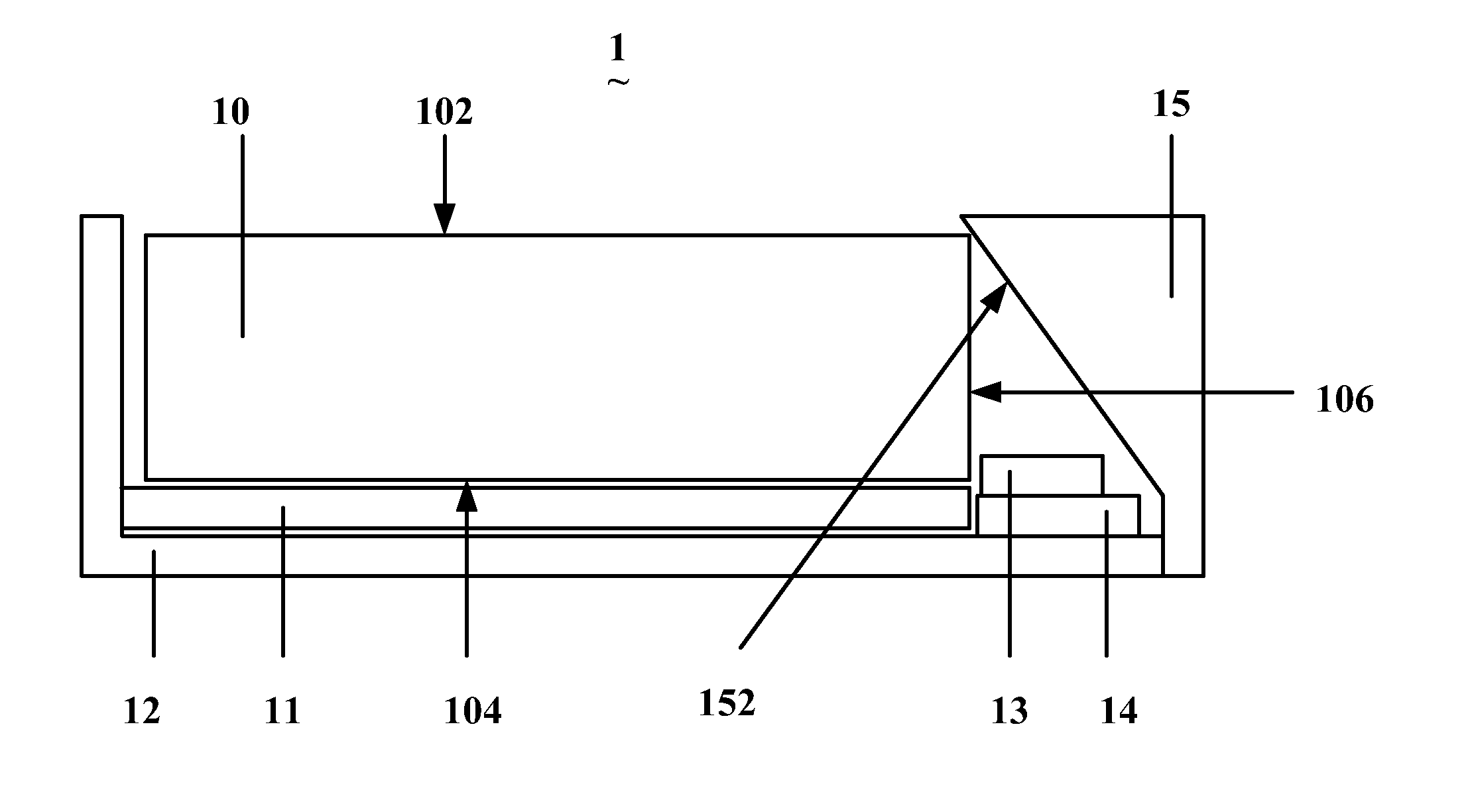
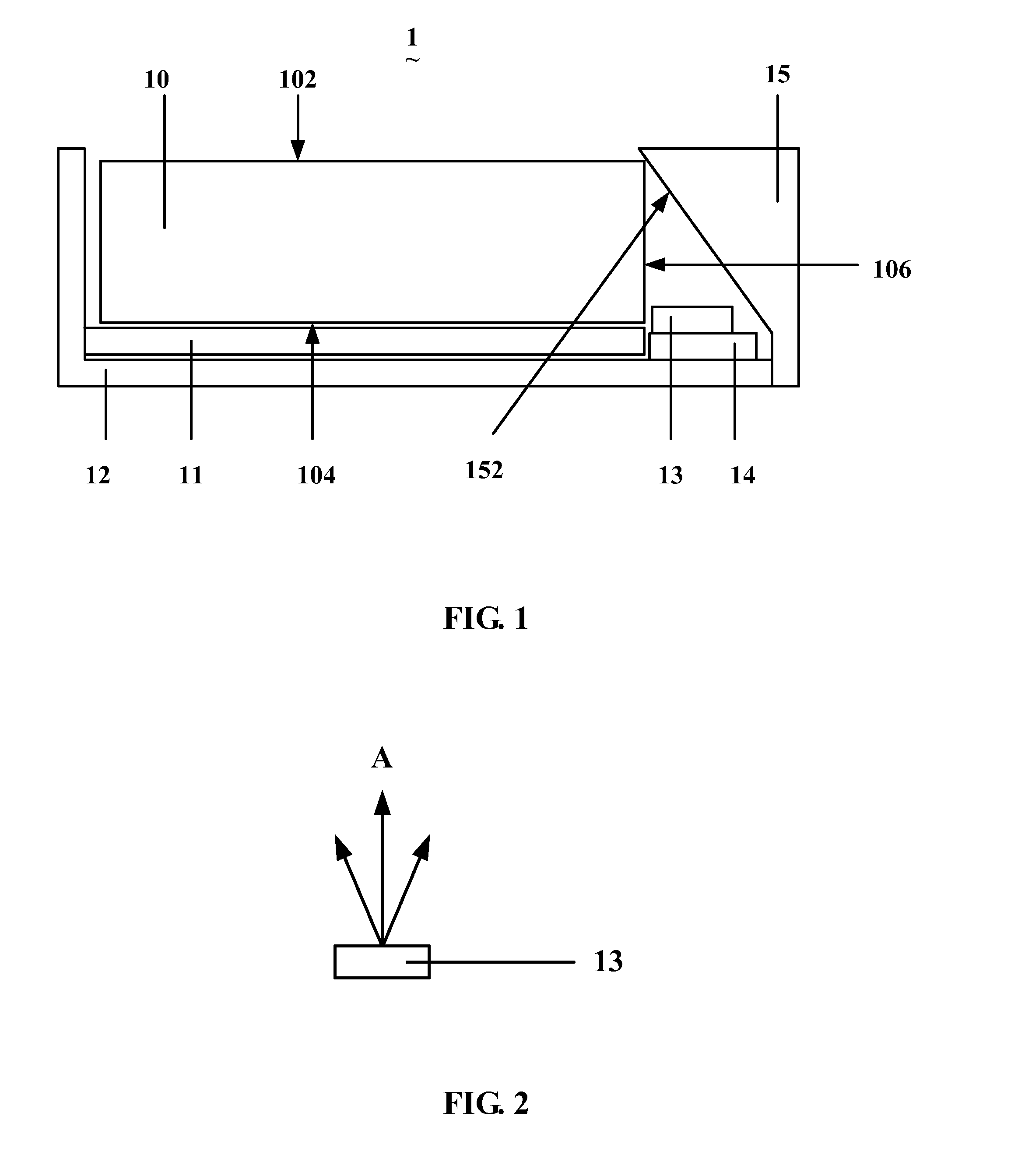
[0036]Referring to FIG. 1, there is shown a schematic side view of a backlight module according to the present disclosure. The backlight module 1 comprises a light guide plate 10, a reflective sheet 11, a backplate 12, a point light source 13, a printed circuit board (PCB) 14 and a baffle 15.

[0037]The light guide plate 10 comprises a top surface 102, a bottom surface 104 and side surfaces 106. The top surface 102 acts as a light exiting surface of the light guide plate 10. The bottom surface 104 and the top surface 102 are disposed opposite to each other. The side surfaces 106 are disposed between the top surface 102 and the bottom surface 104, and one of the side surfaces 106 acts as a light incident surface of the light guide plate 10. The light guide plate 10 may be made of polymethyl methacrylate (PMMA) or polycarbonate (PC).

[0038]The reflective sheet 11 is disposed adjacent to the bottom surface 104 of the light guide plate 10, and mainly functions to reflect light emitted from...

fifth embodiment

[0046]Referring to FIG. 6, there is shown a schematic side view of the backlight module according to the present disclosure. A point light source 53 of the backlight module 5 is fixed to a PCB 54 which is further fixed together with an aluminum extruded piece 56 and, in turn, the aluminum extruded piece 56 makes contact with a front frame 58. A bisector line (not shown) of a light emitting range of the point light source 53 is directed towards a plane in which a bottom surface 504 of a light guide plate 50 is located; and further, the bisector line of the light emitting range of the point light source 53 may be perpendicularly directed towards the plane in which the bottom surface 504 of the light guide plate 50 is located. The front frame 58 is mainly used to accommodate an optical diaphragm assembly 590 and an LCD panel 59 disposed in front of a top surface 502 of the backlight module 5. In this embodiment, the front frame 58 is a metal frame, and a main heat dissipation path for ...


PUM

PropertyMeasurementUnit
inclination angleaaaaaaaaaa
angleaaaaaaaaaa
thicknessaaaaaaaaaa

Abstract

A backlight module is disclosed, which comprises a light guide plate, a point light source and a substrate. The light guide plate comprises a top surface and a bottom surface opposite to each other and a side surface located between the top surface and the bottom surface. The point light source is disposed on the substrate. The backlight module further comprises a backplate, a front frame and a first reflective unit. The backplate is adapted to accommodate the light guide plate. The front frame is disposed adjacent to the top surface of the light guide plate. The point light source is disposed adjacent to the side surface. A bisector line of a light emitting range of the point light source is directed towards a plane in which the top surface or the bottom surface of the light guide plate is located. The first reflective unit is adapted to reflect light emitted from the point light source into the light guide plate. A liquid crystal display (LCD) device comprising the backlight module is further provided in the present disclosure. The backlight module and the LCD device of the present disclosure feature a narrow frame and can dissipate heat easily.

Description

FIELD OF THE INVENTION[0001]The present disclosure generally relates to a backlight module, and more particularly, to a backlight module with a point light source; and the present disclosure further relates to a liquid crystal display (LCD) device comprising the backlight module.BACKGROUND OF THE INVENTION[0002]Owing to their advantages such as having a low radiation level, a light weight, a thin profile and low power consumption, liquid crystal display (LCD) devices have found wide applications in mobile phones, personal digital assistants (PDAs), notebook computers, personal computers (PCs), TV sets and the like. Because liquid crystal molecules in an LCD panel do not emit light by themselves, an area light source device (e.g., a backlight module) must be provided for the LCD panel in order to accomplish the displaying function. The area light source device is mainly used to provide an area light source with sufficient and uniformly distributed luminance for the LCD panel.[0003]In...

Claims


Application Information

Patent Timeline
Patent Type & Authority Applications(United States)
IPC IPC(8): G02F1/13357G09F13/18
CPCG09F13/18G02B6/0011G02B6/0091G02B6/0085G02B6/0031
Inventor HUANG, JIAN-FA
Owner TCL CHINA STAR OPTOELECTRONICS TECH CO LTD
Why Eureka
Try Eureka