
Backlight Module of Display Device

a backlight module and display device technology, applied in the direction of instruments, lighting and heating apparatus, planar/plate-like light guides, etc., can solve the problems of high yield rate, affecting the reflection of led light, high cost, etc., and achieve the effect of improving heat transfer efficiency of backlight source and simple structur

Active Publication Date: 2013-05-23
SHENZHEN CHINA STAR OPTOELECTRONICS TECH CO LTD
View PDF7 Cites 10 Cited by
  • Summary
  • Abstract
  • Description
  • Claims
  • Application Information

AI Technical Summary

Benefits of technology

The present invention aims to provide a backlight module for display devices that has a simple structure and ensures efficient heat transfer between the light guide plate and the backlight source. The invention improves the light reflection hood to eliminate the issue of manual mounting and ensures the completeness of light reflection, thereby improving the light emission efficiency of the guide plate. This enhances the overall performance of the display device.

Problems solved by technology

However, the cost is high and this makes generally available for TV modules that require great brightness.
Manually mounting may cause a problem in yield rate, and thus affecting reflection of LED light and lowering light emission efficiency.
Further, heat dissipation is another issue of backlight modules that requires constant improvement.

Method used


Image

  • Backlight Module of Display Device
  • Backlight Module of Display Device
  • Backlight Module of Display Device

Examples


Embodiment Construction

[0023]To further expound the technical solution adopted in the present invention and the advantages thereof, a detailed description is given to a preferred embodiment of the present invention and the attached drawings.

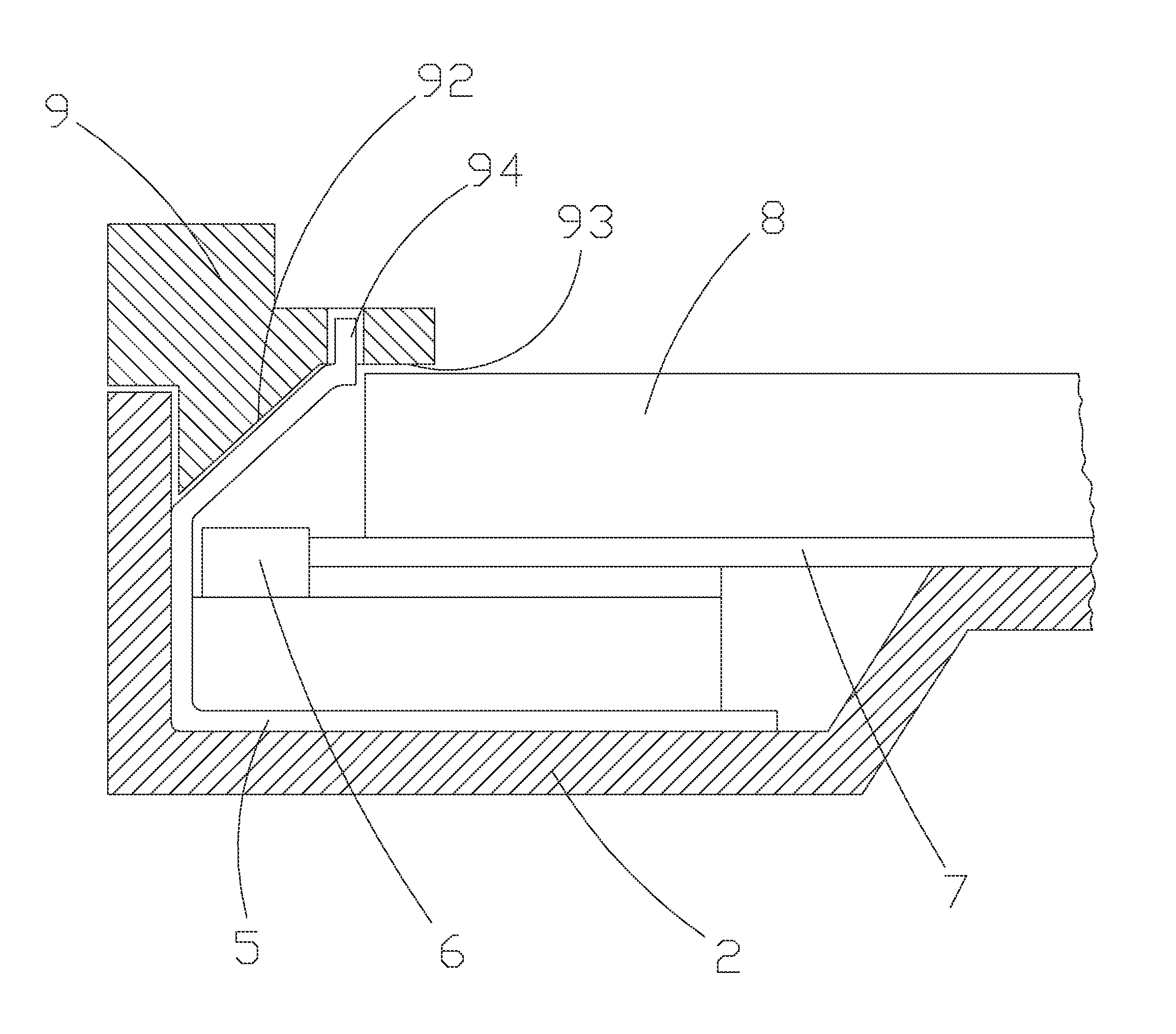
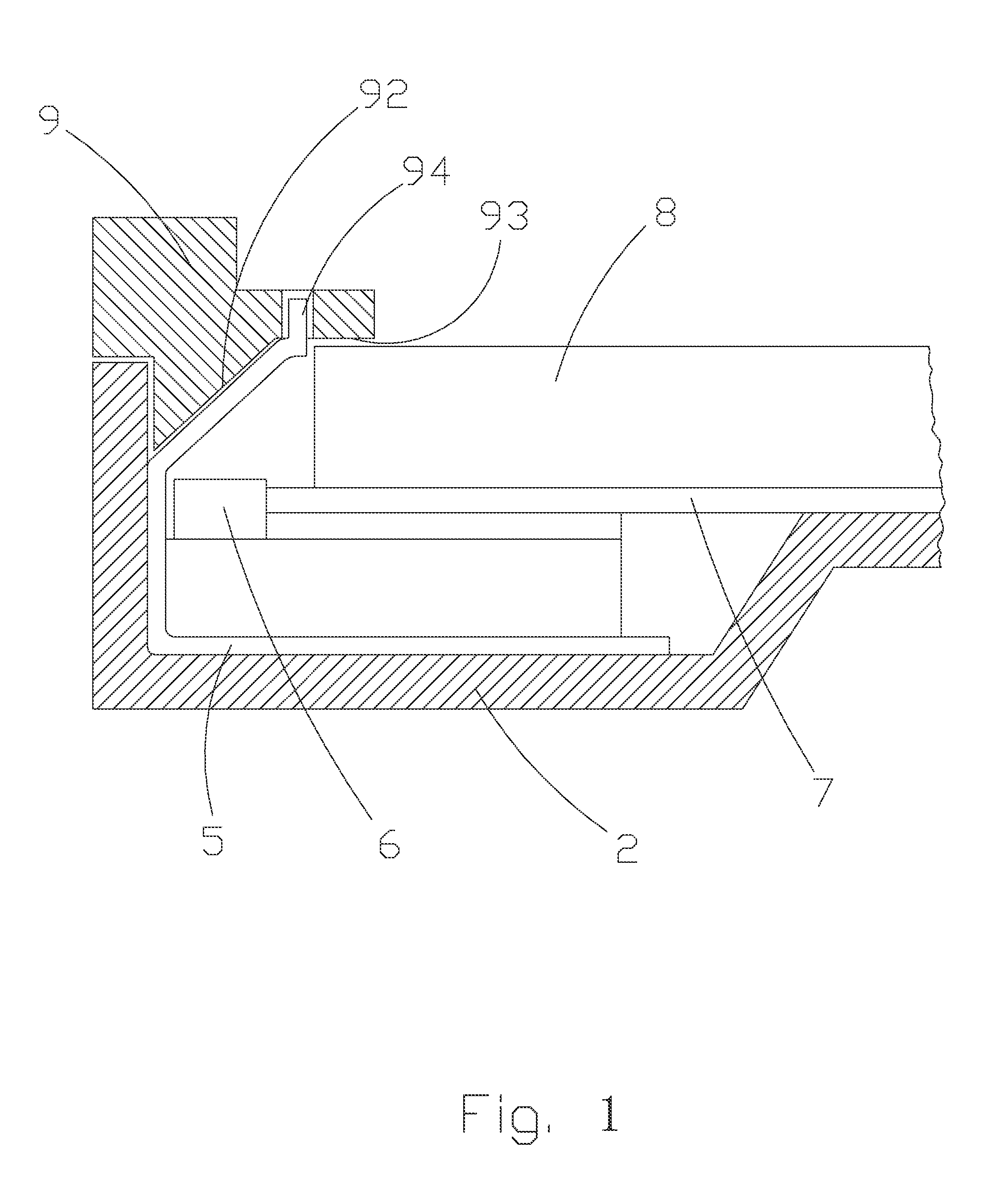
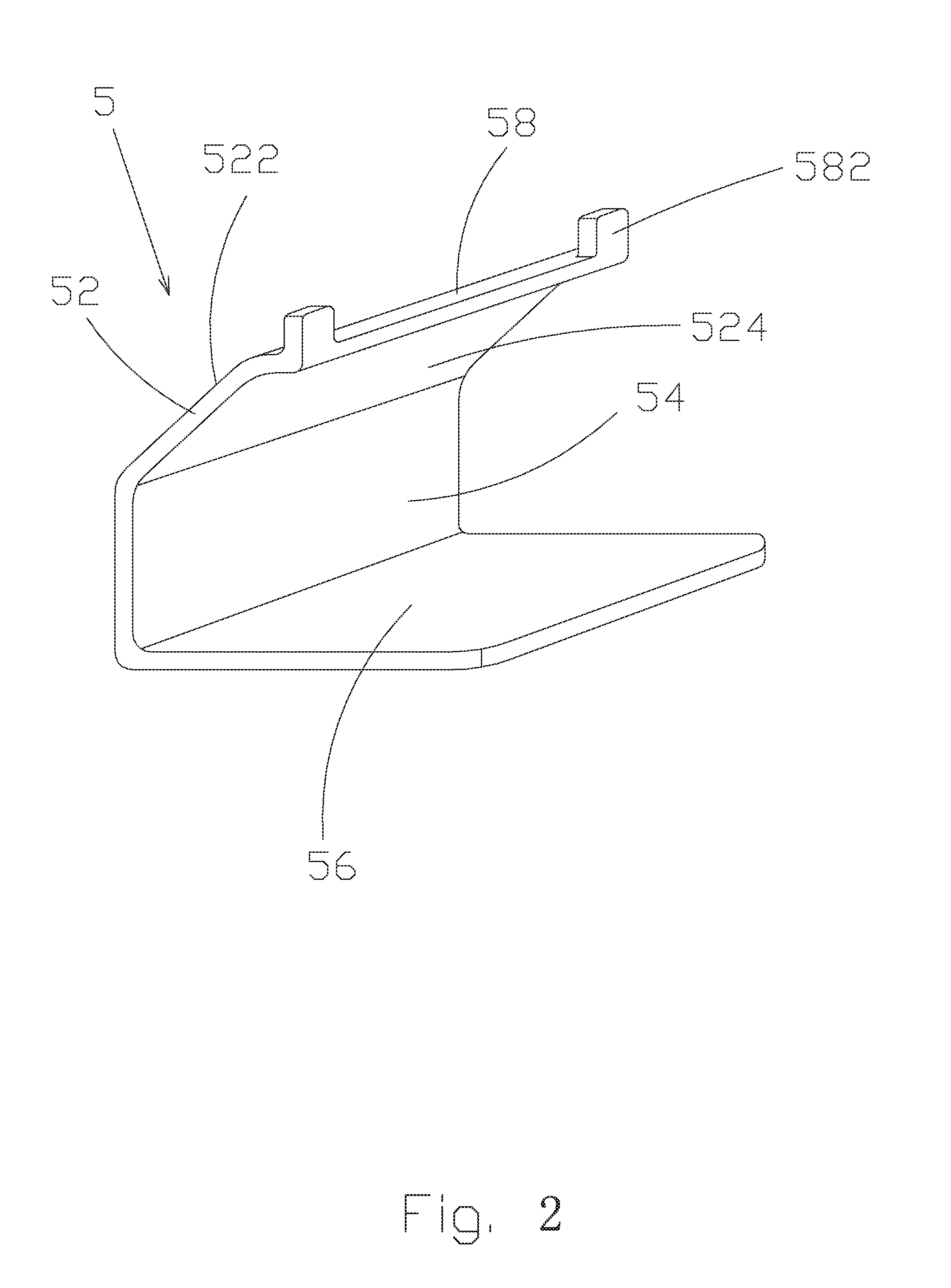
[0024]Referring to FIGS. 1 and 2, the present invention provides a backlight module of display device, which comprises: a back panel 2, a reflection hood 5 arranged on the back panel, a backlight source 6 arranged on the reflection hood 5, a reflector board 7 arranged on the back panel 2, a light guide plate 8 arranged on the reflector board 7, and a plastic frame 9 coupled to the back panel 2 and the light guide plate 8. The backlight source 6 used in the present invention is an LED (Light-Emitting Diode) light strip. Light emitting from the backlight source 6 is reflected by the reflection hood 5 into the light guide plate 8 so as to provide sufficient irradiation of light to the light guide plate 8.

[0025]The back panel 2 has a bottom surface 22 at a location corresp...


PUM


Abstract

The present invention provides a backlight module of display device, which includes: a back panel, a reflection hood arranged on the back panel, a backlight source arranged on the reflection hood, a reflector board arranged on the back panel, a light guide plate arranged on the reflector board, and a plastic frame coupled to the back panel and the light guide plate. Light emitting from the backlight source is reflected by the reflection hood into the light guide plate. The reflection hood includes a reflection section, an abutment section connected to the reflection section, and a bearing section connected to the abutment section. The abutment section is positioned against the back panel. The backlight source is mounted on the bearing section. The bearing section is positioned on the back panel. The backlight module of display device according to the present invention provides a light reflection hood to replace manual mounting of reflection surface thereby eliminating the yield problem caused by manual mounting operation and ensuring completeness of light reflection of the backlight source and thus ensuring light emission efficiency of the light guide plate while improving heat transfer performance of the backlight source.

Description

BACKGROUND OF THE INVENTION[0001]1. Field of the Invention[0002]The present invention relates to a backlight module of display device, and in particular to a backlight module of a display device that ensures completeness of reflected light and also improves heat conduction performance of backlight source.[0003]2. The Related Arts[0004]An LED (Light-Emitting Diode) backlight module is generally classified as two types according to the position of light source, namely direct type and edge type. In backlighting of direct type, the light source is located exactly below an LCD (Liquid Crystal Display) panel for direct irradiation. Since it is possible to use a large number of light tubes, extremely high brightness can be realized. However, the cost is high and this makes generally available for TV modules that require great brightness. Backlighting of edge type positions a light source at an edge of a light guide plate and light from the light source is guided into the interior of the li...

Claims


Application Information

Patent Timeline
IPC IPC(8): F21V7/04
CPCG02F2001/133317G02F1/133308G02F1/133317G02B6/0021G02B6/0023G02B6/0031G02B6/0055G02B6/0091
Inventor TANG, GUOFU
Owner SHENZHEN CHINA STAR OPTOELECTRONICS TECH CO LTD
Learn More