
Linear compressor

a compressor and linear technology, applied in the direction of positive displacement liquid engine, piston pump, magnetic circuit shape/form/construction, etc., can solve the problems of significant mechanical loss, inability to meet the low-capacity simple construction requirements, and inability to apply conventional linear compressors and linear motors thereto. to achieve the effect of increasing the constant of magnetic springs, reducing the moving distance of permanent magnets, and simplifying the shape of the motor cover

Active Publication Date: 2013-05-23
LG ELECTRONICS INC
View PDF5 Cites 19 Cited by
  • Summary
  • Abstract
  • Description
  • Claims
  • Application Information

AI Technical Summary

Benefits of technology

The present invention provides a linear compressor that can achieve a light weight or a small size by integrating or removing components, by changing the construction of a linear motor. The linear motor is designed to perform reciprocal linear motion between the inner stator and one pole of the outer stator, which increases the magnetic spring constant and decreases the moving distance of the permanent magnets, resulting in a reduction in the stroke controlling cooling capacity. Additionally, the motor characteristic value and the magnetic spring constant can offset each other, further reducing the stroke. The linear compressor has advantages such as low capacity, light weight, and small size.

Problems solved by technology

Recently, since the conventional reciprocal compressor includes components such as a crank shaft, etc. to convert a rotation force of a driving motor into a reciprocal linear motion force of the piston, a problem such as a significant mechanical loss occurs due to the motion conversion.
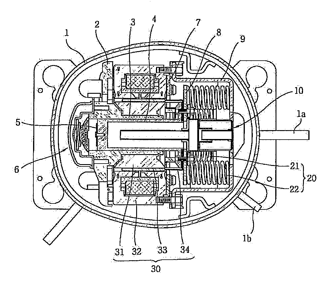
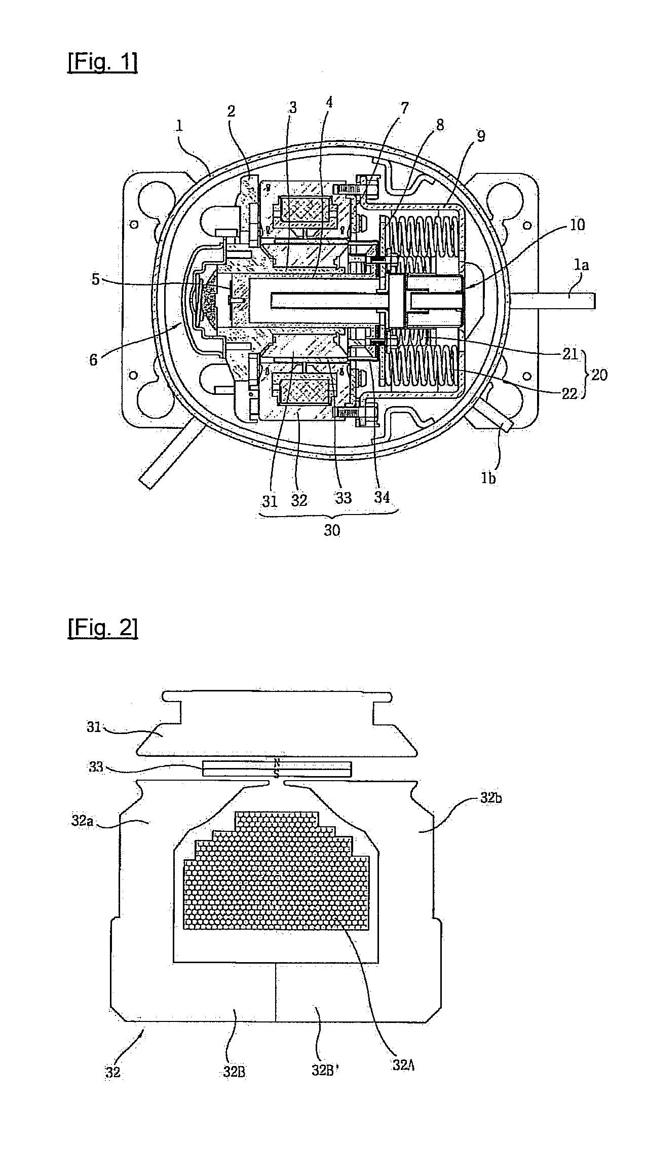
However, the conventional linear compressor and the linear motor applied thereto are not suitable for the low-capacity simple construction because the stroke length of the piston 4 is strictly limited to the distance in which the center of the permanent magnet 33 performs reciprocal linear motion between the two poles 32a and 32b of the outer stator 32 due to the aforementioned reasons and a few springs 20 are used for this purpose.

Method used


Image

  • Linear compressor
  • Linear compressor
  • Linear compressor

Examples


Embodiment Construction

[0045]Hereinafter, preferred embodiments of a linear compressor according to the present invention will be described in detail with reference to the accompanying drawings.

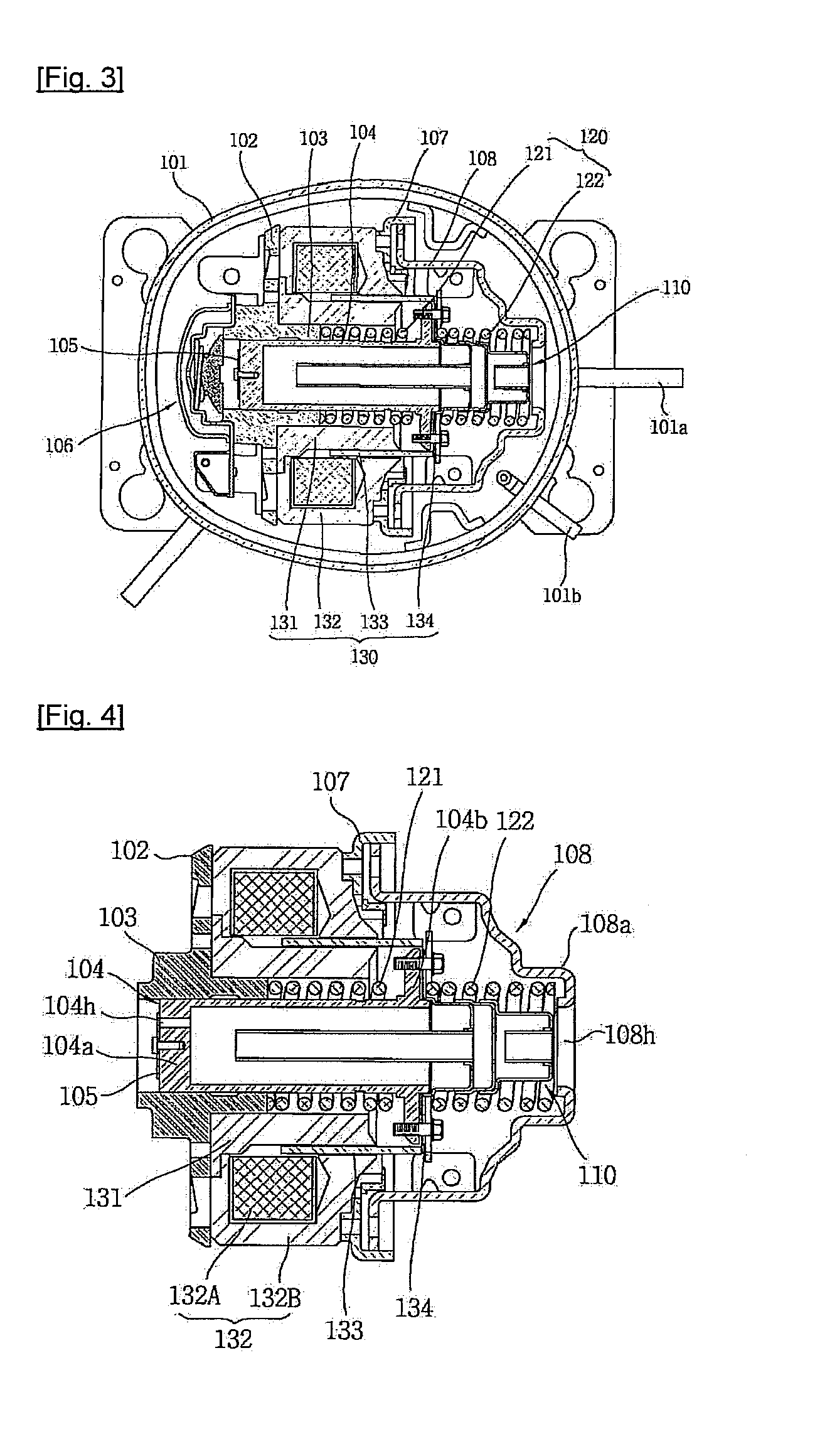
[0046]FIG. 3 is a top sectional view illustrating an example of the linear compressor according to the present invention, and FIG. 4 is a side sectional view illustrating an example of a structure body of the linear compressor according to the present invention.

[0047]As illustrated in FIGS. 3 and 4, the linear compressor according to the present invention is configured such that a structure body composed of a frame 102, a cylinder 103, a piston 104, a suction valve 105, a discharge valve assembly 106, a motor cover 107, a back cover 108, a suction muffler 110, two springs 120 (121 and 122), and a linear motor 130 is elastically supported in a hermetic container 101 provided with a suction pipe 101a and a discharge pipe 101b through which refrigerant is sucked and discharged.

[0048]The frame 102 and the cylinder 103 ...


PUM


Abstract

A linear compressor according to the present invention can prevent leakage of a magnetic force by changing the construction of a linear motor. As the construction of the linear motor is changed, a mechanical spring constant is set smaller in consideration of a magnetic spring constant, so that the size of springs supporting a piston in the reciprocal linear motion direction can be reduced and components supporting the springs can be removed. Therefore, the linear compressor achieves a small size / a light weight. With the characteristics of the linear motor construction, the linear compressor can suppress a stroke spreading influence and easily expand a compression capacity according to a load.

Description

[0001]TECHNICAL FIELD[0002]The present invention relates to a linear compressor which can not only meet requirements such as a low compression capacity and a small installation space but also can ensure high efficiency, and a linear motor applied to the linear compressor, and more particularly, to a linear compressor which can not only prevent leakage of a magnetic force but also can employ a magnetic spring constant, and a linear motor applied to the linear compressor.BACKGROUND ART[0003]In general, a reciprocal compressor is configured such that a compression space into / from which an operating gas is sucked and discharged is defined between a piston and a cylinder and that the piston is linearly reciprocated in the cylinder to compress refrigerant.[0004]Recently, since the conventional reciprocal compressor includes components such as a crank shaft, etc. to convert a rotation force of a driving motor into a reciprocal linear motion force of the piston, a problem such as a signific...

Claims


Application Information

Patent Timeline
Patent Type & Authority Applications(United States)
IPC IPC(8): F04B35/04
CPCF04B35/045F04B39/0005F04B35/04H02K33/16H02K33/06F04B17/04H02K1/34H02K16/04H02K33/02
Inventor SONG, KI WOOKCHOI, JONG YOONCHOI, CHEAL LAK
Owner LG ELECTRONICS INC
Learn More