Device for Connecting a Line Element to a Component

a line element and component technology, applied in the direction of manufacturing tools, electrical generators, pipe heating/cooling, etc., can solve the problems of difficult heating in the region of possible connection elements, the pipe itself can be heated, etc., and achieve the effect of convenient use, cost-effectiveness and simple structur

Active Publication Date: 2013-05-23
CELLCENTRIC GMBH & CO KG
View PDF2 Cites 4 Cited by
  • Summary
  • Abstract
  • Description
  • Claims
  • Application Information

AI Technical Summary

Benefits of technology

[0008]According to an exemplary embodiment of the present invention the material of the connection housing surrounds the heated line section and the heating wire over the whole length of the line section. The heating wire can thus be wound around the line section correspondingly from externally so that no reaction of a medium conveyed in the line section with the possibly very hot heating wire can occur. In addition, due to the fact that the material of the connection housing surrounds both the heating wire and the line section, this can be correspondingly protected against damage. The connection housing or the material of the connection housing thus form a protective layer around the line section provided with the heating wire. This is then protected from mechanical damage so that the heating can be securely and reliably guaranteed.
[0009]According to a further advantageous embodiment of the device according to the invention the connection housing is formed from an electrically non-conductive material. Such a connection housing composed of an electrically non-conductive material can also provide, additionally or alternatively to the abovementioned mechanical protection of the line element and / or heating wire, an electrical insulation of the heating wire in relation to the environment so that, besides the heating wire and the line section, merely the material of the connection housing is necessary as a third layer. The structure is correspondingly simple and can be cost-effectively realized.
[0010]According to an advantageous further development of the device according to the invention the connection housing is formed integrally with the line element. Such a structure can be used, for example, when line elements with a pre-finished length are used in comparatively large numbers. The line element and the connection housing can then be easily formed integrally so that in the region in which the line element goes into the connection housing, no additional interfaces are produced that could be critical in terms of sealing and possibly in relation to the transmission of electrical heat energy from the region of the connection housing into the region of the line element.
[0011]According to a particularly favorable embodiment of the device according to the invention, the connection housing is formed as an injection molded part, which surrounds an end of the line element and the line section on the outer periphery. Such a structure as an injection molded part, in particular made of plastic, can be easily used to produce a comparatively stable and cost-effective connection housing if correspondingly high numbers of connection housings are required. Due to the fact that the connection housing or the injection molded material of the connection housing completely surrounds an end of the line element and the line section, a sealed connection can be produced very simply and efficiently through this structure. Additionally, the line section can be embedded together with the heating wires in the injection molded part insofar as this structure is to be used in the above-described variant. A component is then produced with a single work step on an injection molding unit which brings together all the aforementioned variants and advantages.
[0012]As already indicated above, according to a further very advantageous embodiment of the device according to the invention, the line element itself can also be designed to be electrically heated. It can thereby be particularly meaningful and advantageous if the electrical heating both of the line element and of the connection housing is designed so that the heating wire extending in the region of the line section is also connected to a heating wire extending in the region of the line element.
[0013]According to a very favorable and advantageous development of the present invention, the electrical connections for the heating wire are guided outwards in the region of the connection housing. This facilitates the electrical connection of the heating wire in the region of the connection housing. As the connection housing is releasably connected to a component, it is generally at a fixedly predefined location during the operation of a system equipped with the device and, unlike a line element formed, for example, as a tube, is typically not moved by vibrations and the like. In this region an arrangement of the electrical connection elements can thereby take place comparatively simply, securely and reliably without these being exposed to the risk of damage through constant movements.

Problems solved by technology

The problem with this structure is that the pipe itself can be heated.
Heating is thereby difficult in the region of possible connection elements, in particular if the heated line element is attached to an unheated component, for example a fuel cell stack, a reactor, a water separator or similar.

Method used


Image

  • Device for Connecting a Line Element to a Component
  • Device for Connecting a Line Element to a Component

Examples


Embodiment Construction

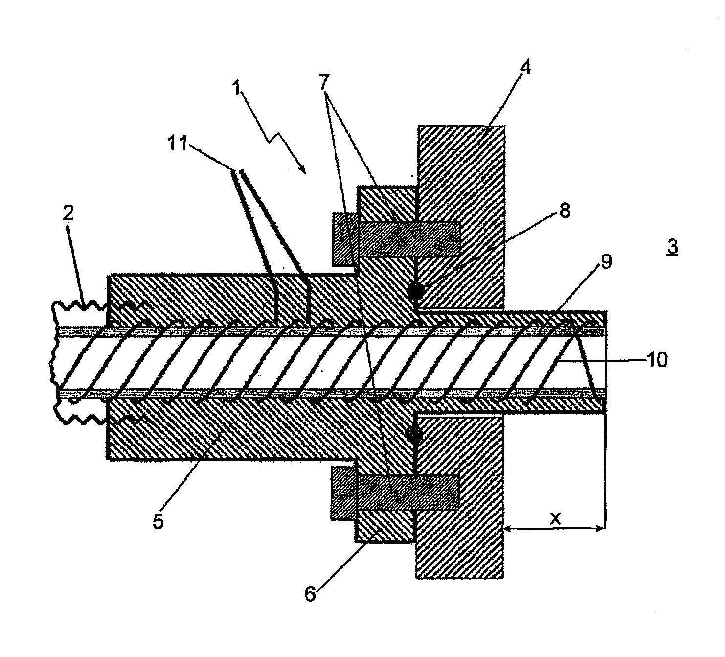
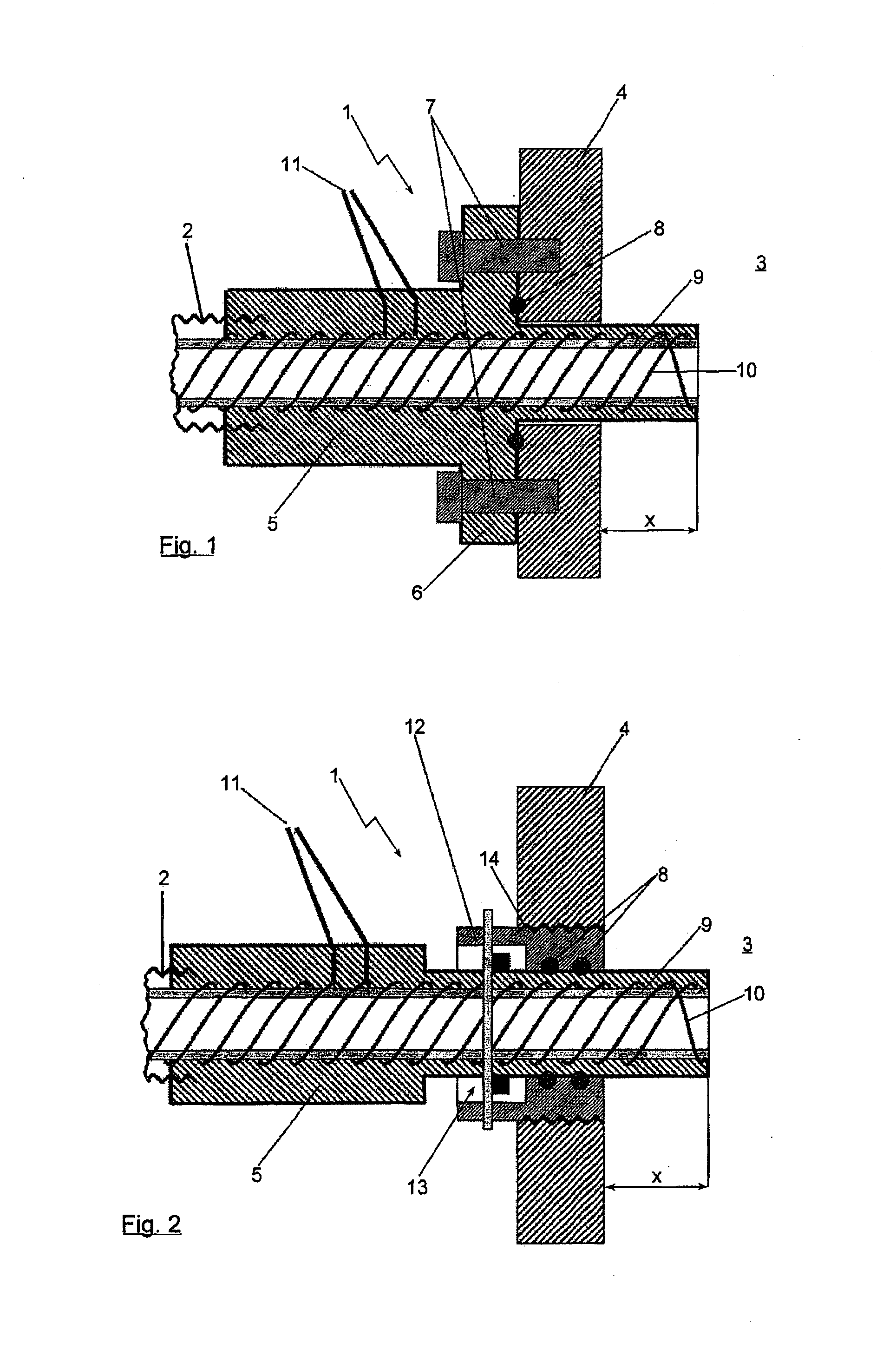
[0018]The device according to the invention will be described below by reference to the two figures in two possible exemplary embodiments. The structure can provide heating for example in fuel cell systems but also in all other systems, in which heated lines are connected via interfaces to components.

[0019]In the illustration of FIG. 1, a first embodiment of the device 1 according to the invention for connecting a line element 2 to a component 3 can be seen. The line element 2 is thereby shown, for example, as a section of a corrugated tube. Having regard to the component 3, whereby the reference numeral 3 denotes the inside of the component 3 here, merely a wall 4 thereof is explicitly shown in the illustration. The device 1 comprises a connection housing 5. This connection housing 5 comprises a flange 6, which is screwed via two fixing screws 7 to the wall 4 of the component 3. The connection housing 5 is thus releasably connected to the component 3. For sealing, a sealing element...


PUM

PropertyMeasurementUnit
lengthaaaaaaaaaa
electrically non-conductiveaaaaaaaaaa
electricalaaaaaaaaaa

Abstract

A device for connection of a line element to a component is provided. The line element ends in a connection housing or is connected to such a connection housing. A releasable fixing arrangement is configured between the connection housing and the component. A line section extending in the connection housing is heated by an electric heating wire. The heating wire externally surrounds the line section. The heated line section projects in the direction of the component so far over the region for releasable fixing of the connection housing on the component that it ends in the inner space of the component.

Description

BACKGROUND AND SUMMARY OF THE INVENTION[0001]Exemplary embodiments of the present invention relate to a device for connecting a line element to a component and a fuel cell system having at least one component comprising such a line element.[0002]German Patent Document DE 10 2007 009 898 A1 discloses a heating system for a pipe or a tube in a fuel cell system. A heating wire in contact with the pipe or tube in order to prevent water from freezing in the pipe or tube. The heating wire is, for example, wound around the pipe or tube and is fixed thereto via a protective layer. In addition, a thermal insulation can be provided.[0003]The problem with this structure is that the pipe itself can be heated. Heating is thereby difficult in the region of possible connection elements, in particular if the heated line element is attached to an unheated component, for example a fuel cell stack, a reactor, a water separator or similar. Condensation and freezing of liquid water can then arise in thi...

Claims


Application Information

Patent Timeline
Patent Type & Authority Applications(United States)
IPC IPC(8): H01R43/00H01M8/04F16L53/38
CPCF16L5/02F16L5/10F16L53/008Y10T29/532H01M8/04201Y02E60/50H01R43/00H01M8/04037F16L53/38
Inventor BAUR, THOMASSTEIN, BORISSTEINHUEBL, SIMON
Owner CELLCENTRIC GMBH & CO KG
Why Eureka
Try Eureka