Crimped terminal

a crimp terminal and open barrel technology, applied in the direction of electrical equipment, connections, connections effected by permanent deformation, etc., can solve the problems of insufficient contact conductivity, insufficient crimping effect, and inability to obtain associated serration b>120/b>, so as to reduce the gap caused, increase the contact conductivity, and smooth flow

Active Publication Date: 2013-05-23
YAZAKI CORP
View PDF2 Cites 4 Cited by
  • Summary
  • Abstract
  • Description
  • Claims
  • Application Information

AI Technical Summary

Benefits of technology

[0016]It is an object of the present invention to provide a crimp terminal capable of maintaining the contact conductivity between a conductor and the terminal continuously high.
[0018]The above aspect can bring about the following effects. That is, when the conductor crimp portion is crimped to the conductor of the electric wire by using the crimp terminal, the conductor of the electric wire, while causing a plastic deformation, enters into each of the small circular recesses provided, as serrations, at the inner surface of the conductor crimp portion, to thereby strengthen the joint between the terminal and the conductor. In this case, the surface of the conductor caused to flow by a pressing force has a frictional mating with the hole edge of each of the small circular recesses or the surface of the conductor entering into the recess causes a frictional mating with the inner periphery side surface of the recess, thereby an oxide film of the surface of the conductor is peeled off and a newly formed surface exposed has a contact conduction with the terminal. In this respect, since many small circular recesses are so provided as serrations, a total length of the hole edge of the recess brings about an effectiveness in scraping off the oxide film, irrespective of the extending direction of the conductor. Thus, the contact conduction effect by the exposure of the newly formed surface can be more increased than when the linear serration intersecting with the direction in which the conductor of the electric wire extends is provided like the associated example. Since the inner periphery corner portion where the inner bottom surface and inner periphery side surface of the small circular recess intersect with each other has the roundness portion in a form of a smooth curve, the conductor having entered into the recess is caused smoothly flow along the roundness portion, thus enabling to reduce the gap caused to the inner periphery corner portion. There was such a fear as that, in the case of a large gap, being influenced by thermal shock, mechanical vibration or the like, the oxide film grows with the gap as a start point to thereby lower the contact conductivity between the conductor and the crimp terminal. However, capability of reducing the gap can suppress the growth of the oxide film, thus enabling to maintain a good contact conduction performance for a long time.

Problems solved by technology

However, a sufficient contact conductivity was, as the case may be, not necessarily obtained.
However, the associated serration 120 failed to show an effectiveness when the conductor extends in directions other than the longitudinal direction.

Method used


Image

  • Crimped terminal
  • Crimped terminal
  • Crimped terminal

Examples


Embodiment Construction

[0024]Hereinafter, one embodiment of the present invention will be explained with reference to drawings.

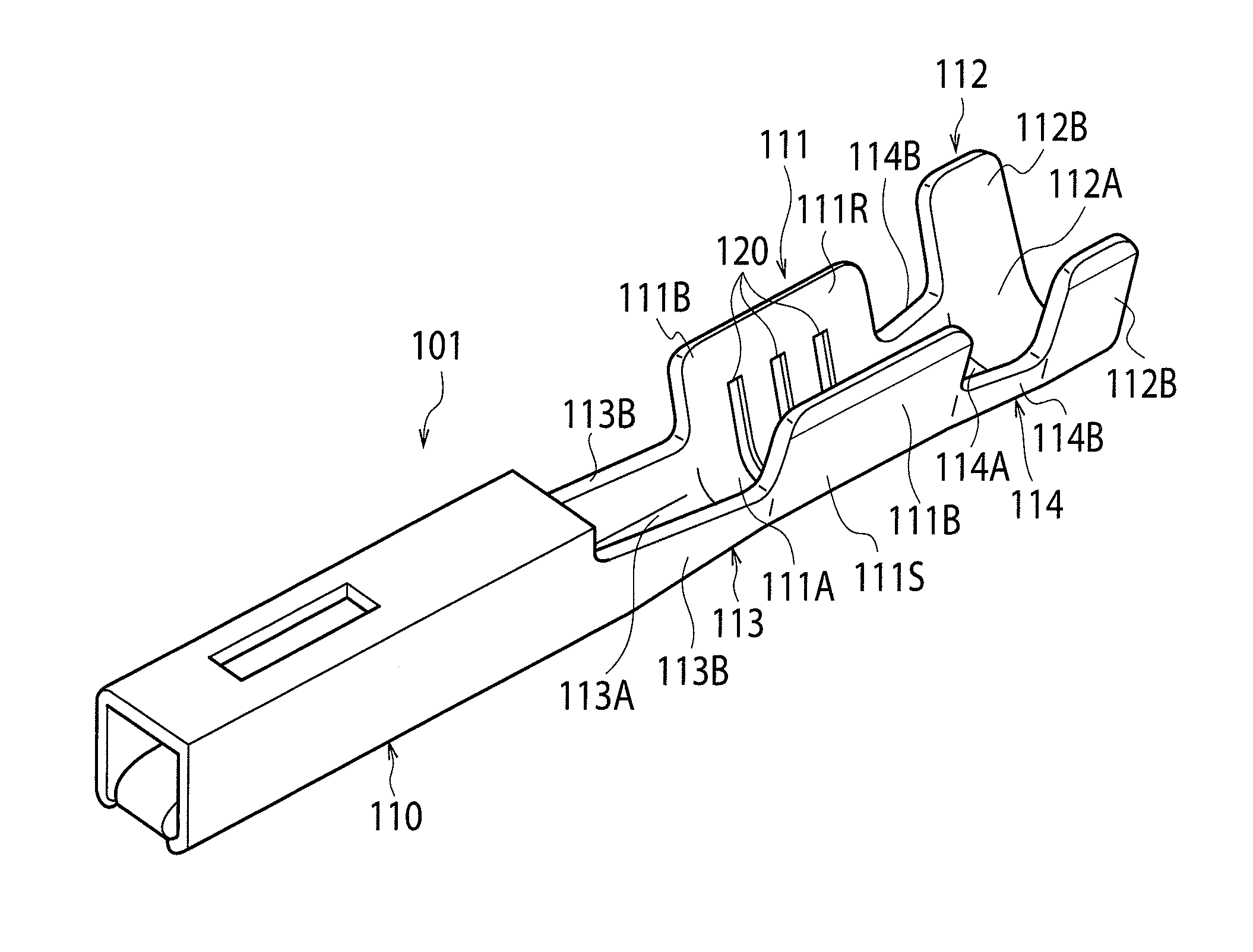
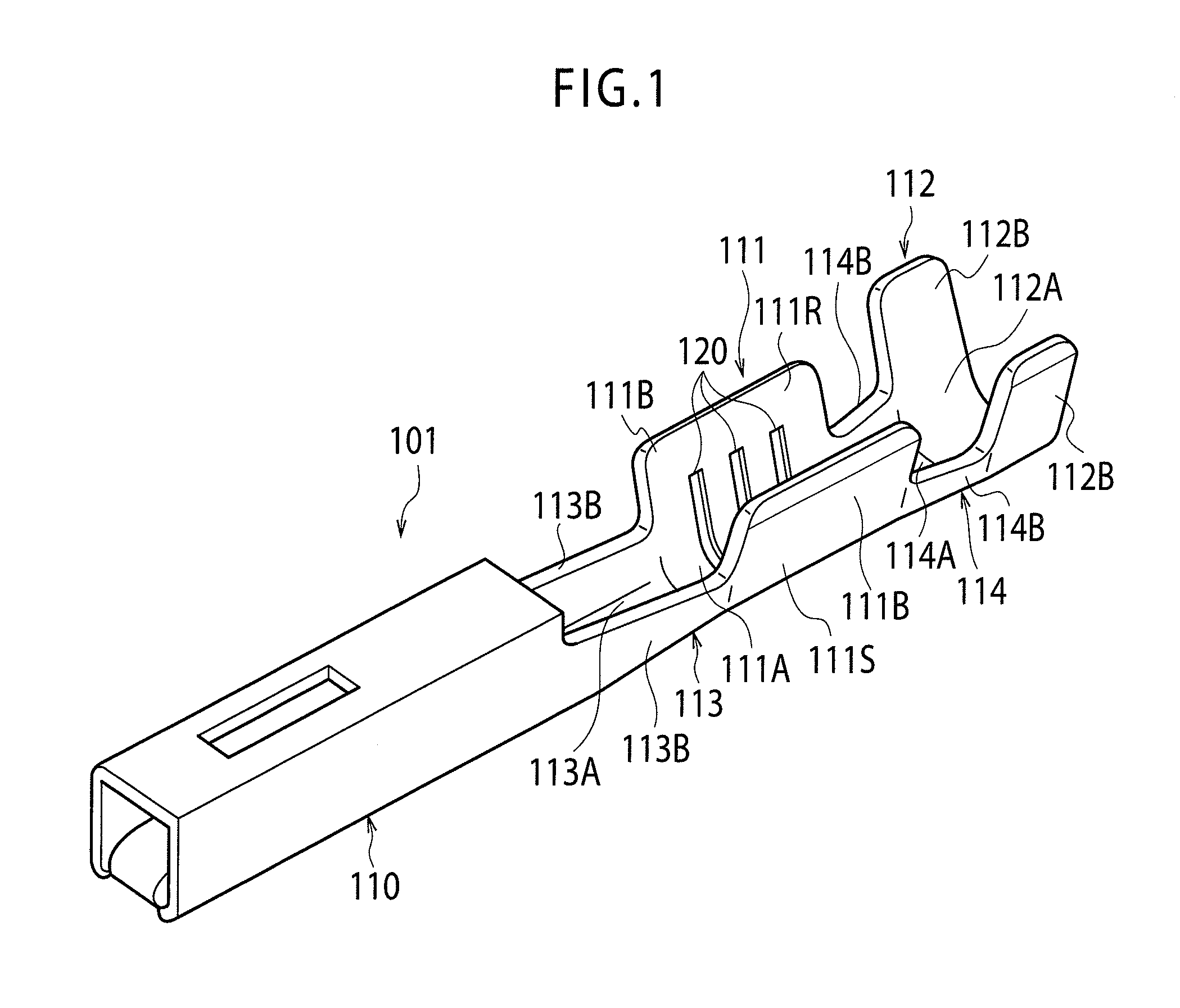
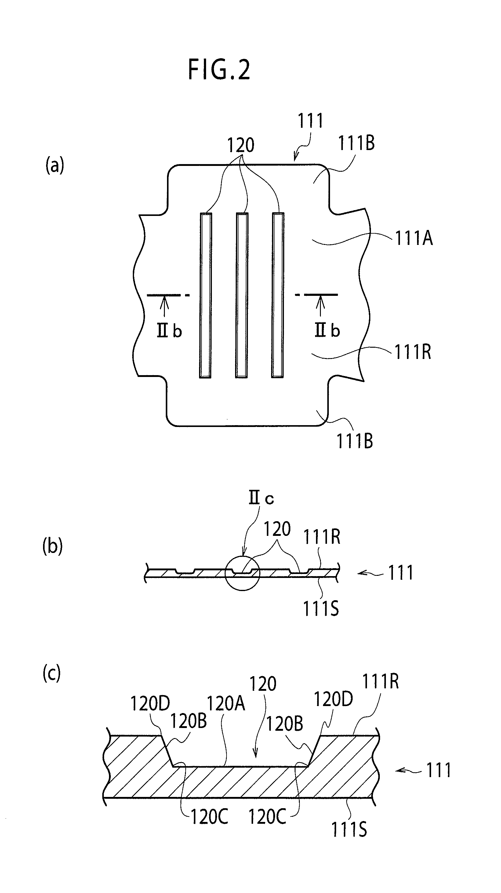
[0025]FIG. 3 is a perspective view showing a structure of a crimp terminal according to the embodiment. FIG. 4 shows a state before a conductor crimp portion of the crimp terminal is crimped, where FIG. 4(a) is a developed plan view, FIG. 4(b) is a cross sectional view taken along the line IVb-IVb in FIG. 4(a), and FIG. 4(c) is an enlarged view of a portion IVc in FIG. 4(b).

[0026]As shown in FIG. 3, a crimp terminal 1 is one of a female type and has such a structure as that, in the front portion in the longitudinal direction (also the longitudinal direction of a conductor of an electric wire to be connected, that is, a direction in which the electric wire extends) of the terminal, there is provided a box-type electrical connection portion 10 to be connected to a male terminal on a mating connector side, behind the electrical connection portion 10, there is provided a conductor cri...


PUM


Abstract

A conductor crimp portion (11) before being crimped to a conductor (Wa) of an electric wire includes, in an inner surface (11R) of the conductor crimp portion (11), circular recesses (20) as serrations of the conductor crimp portion (11) scattered to be spaced from each other. At an inner periphery corner portion where an inner bottom surface (20A) and an inner periphery side surface (20B) of each of the recesses (20) intersect with each other, a roundness portion (20C) for connecting the inner bottom surface (20A) with the inner periphery side surface (20B) by a smooth continuous curved surface are provided.

Description

TECHNICAL FIELD[0001]The present invention relates, for example, to an open barrel type crimp terminal used for an electric system of an automobile and having a conductor crimp portion having a U-shape cross section.BACKGROUND ART[0002]FIG. 1 is a perspective view showing a structure of an associated crimp terminal described, for example, in PTL 1.[0003]A crimp terminal 101 has such a structure that, in the front portion in the longitudinal direction of a terminal (also the longitudinal direction of a conductor of an electric wire to be connected), there is provided an electrical connection portion 110 to be connected to a terminal of a mating connector side, behind the electrical connection portion 110, there is provided a conductor crimp portion 111 to be crimped to an exposed conductor of an end of an electric wire (not shown), and still behind the conductor crimp portion 111, there is provided a coated crimping portion 112 to be crimped to the electric wire's portion coated with...

Claims


Application Information

Patent Timeline
Patent Type & Authority Applications(United States)
IPC IPC(8): H01R4/28
CPCH01R4/185H01R4/28H01R4/188
Inventor ONUMA, MASANORITAKEMURA, KOUSUKE
Owner YAZAKI CORP
Why Eureka
Try Eureka