Battery system

Inactive Publication Date: 2013-05-30
SAKAKIBARA KAZUYUKI
View PDF3 Cites 39 Cited by
  • Summary
  • Abstract
  • Description
  • Claims
  • Application Information

AI Technical Summary

Problems solved by technology

However, for the use of such a commercial power source, its electrical outlet may be located at a limited number of particular positions, and a user of the commercial power source may encounter situations, such as an emergency situation, where the user cannot obtain any electric power from the electrical outlet.

Method used


Image

  • Battery system
  • Battery system
  • Battery system

Examples


Embodiment Construction

[0047]Several presently preferred embodiments of the invention will be described in more detail by reference to the drawings in which like numerals are used to indicate like elements throughout.

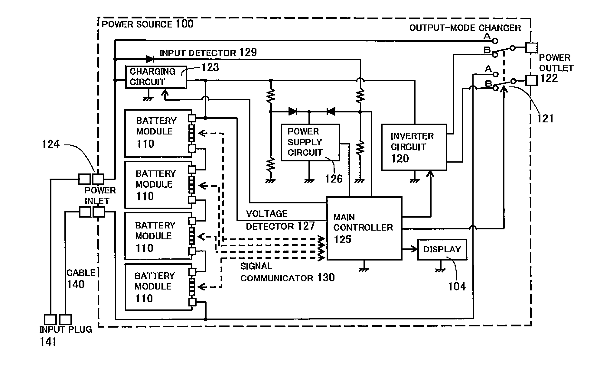
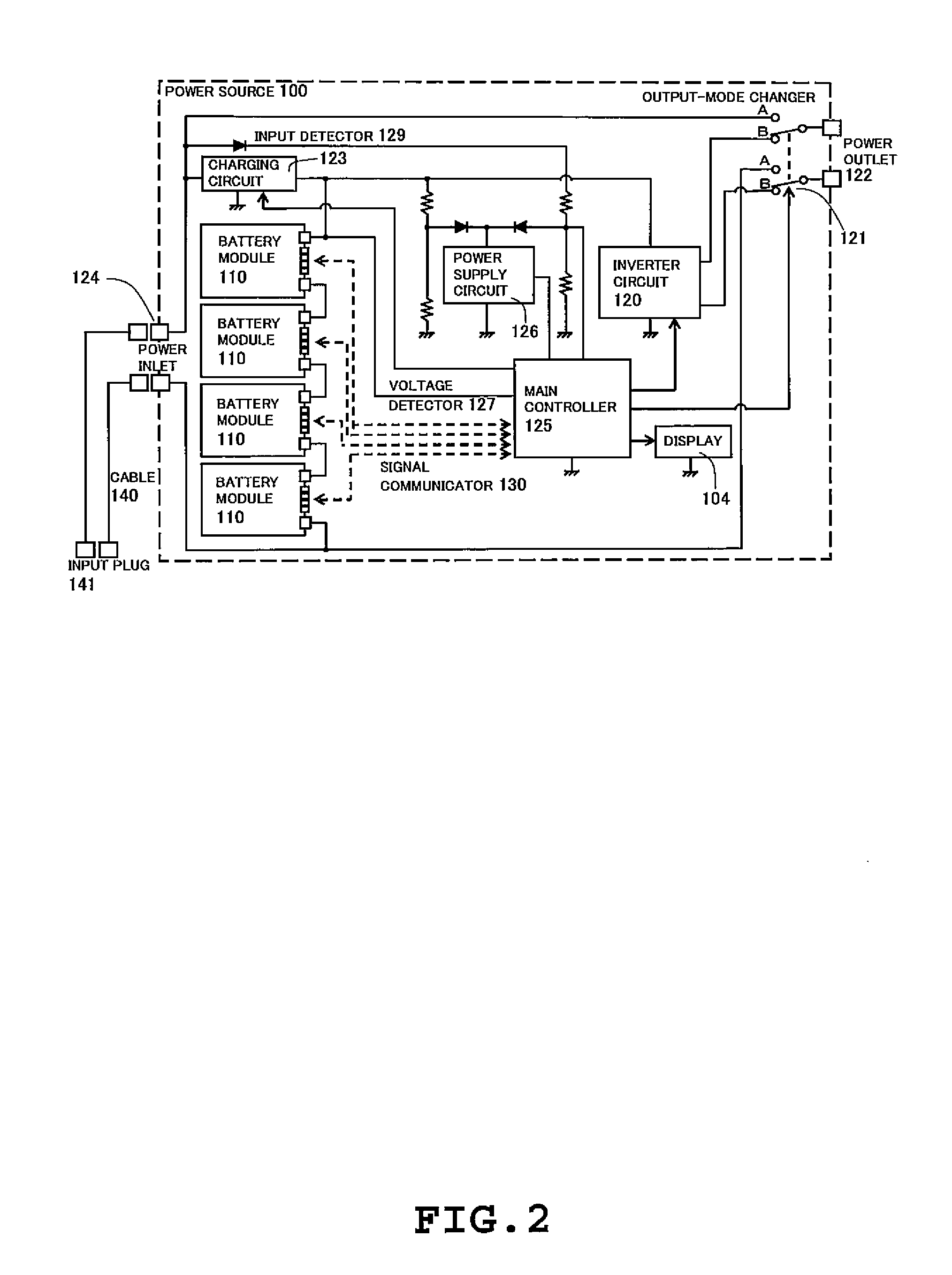
[0048]There will be next described in detail with reference to the drawings, a power source 100 (see FIG. 2) which is one example of a battery system according to an exemplary illustrative embodiment of the invention.

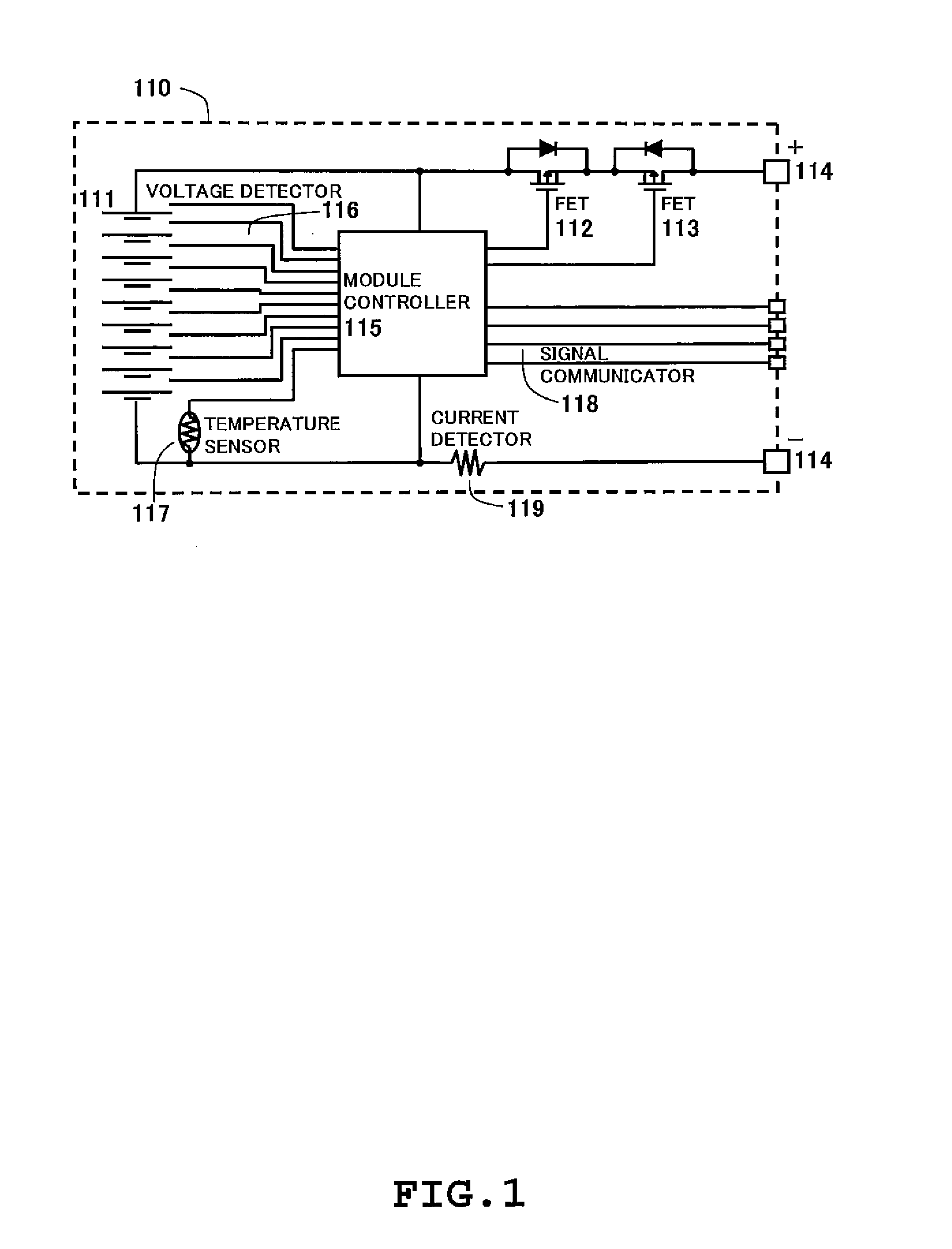
[0049]FIG. 1 is a functional block diagram illustrating a representative one of battery modules 110 that are housed within the power source 100. Each battery module 110 houses nine (9) battery cells 111 (e.g., each in the form of a Li-ion battery).

[0050]The nine (9) battery cells 111 are interconnected in series, and are electrically connected with a battery module terminal (including a plurality of terminal ends) 114 through an FET (Field-Effect Transistor) 112 for battery module charging (i.e., one example of a switching device or a current interrupt device) and an FET 113 for ...


PUM


Abstract

A battery system is disclosed which includes: a battery assembly; an AC-voltage generator for generating alternate current (AC) voltage from direct current (DC) voltage of the battery assembly; a battery charger for charging the battery assembly; and a detector for detecting application of AC voltage from the AC-voltage generator to the battery charger.

Description

CROSS-REFERENCE TO RELATED APPLICATIONS[0001]This application claims the priority benefit of Japanese Patent Application No. 2011-261577, filed Nov. 30, 2011, the content of which is incorporated herein by reference in its entirety.BACKGROUND OF THE INVENTION[0002]1. Field of the Invention[0003]The present invention relates to a battery system, that is, a power source that supplies electric power generated by a rechargeable battery such as a Li-ion battery to an electric device for operation of the electric device.[0004]2. Description of the Related Art[0005]Typically, an electric device is powered by alternate-current (AC) voltage supplied from a commercial power source. However, for the use of such a commercial power source, its electrical outlet may be located at a limited number of particular positions, and a user of the commercial power source may encounter situations, such as an emergency situation, where the user cannot obtain any electric power from the electrical outlet. Fo...

Claims


Application Information

Patent Timeline
Patent Type & Authority Applications(United States)
IPC IPC(8): H02J7/00
CPCH02J7/0068H02J7/0036H02J7/0047H02J7/0048H02J7/0049
Inventor SAKAKIBARA, KAZUYUKI
Owner SAKAKIBARA KAZUYUKI
Why Eureka
Try Eureka