Electrostatic induction power generator

Active Publication Date: 2013-05-30
ORMON CORP
View PDF7 Cites 10 Cited by
  • Summary
  • Abstract
  • Description
  • Claims
  • Application Information

AI Technical Summary

Benefits of technology

[0026]As described above, according to one or more embodiments

Problems solved by technology

However, the semiconductor microfabrication techniques generally require large-scale equipment, and further when producing the electrostatic induction power generators using the sem

Method used


Image

  • Electrostatic induction power generator
  • Electrostatic induction power generator
  • Electrostatic induction power generator

Examples


embodiment 1

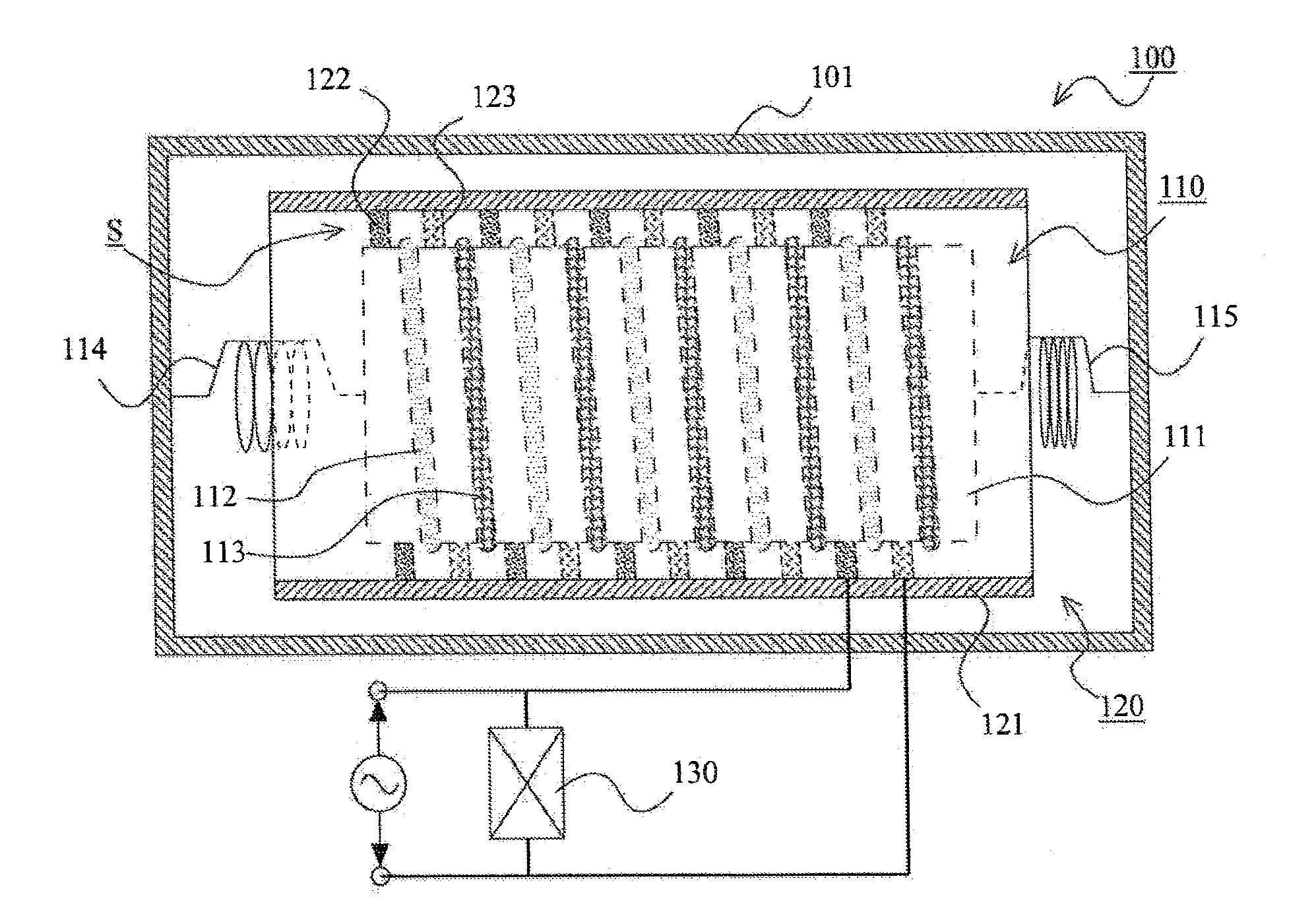
[0041]An electrostatic induction power generator according to Embodiment 1 of the present invention will be described with reference to FIGS. 1 to 6.

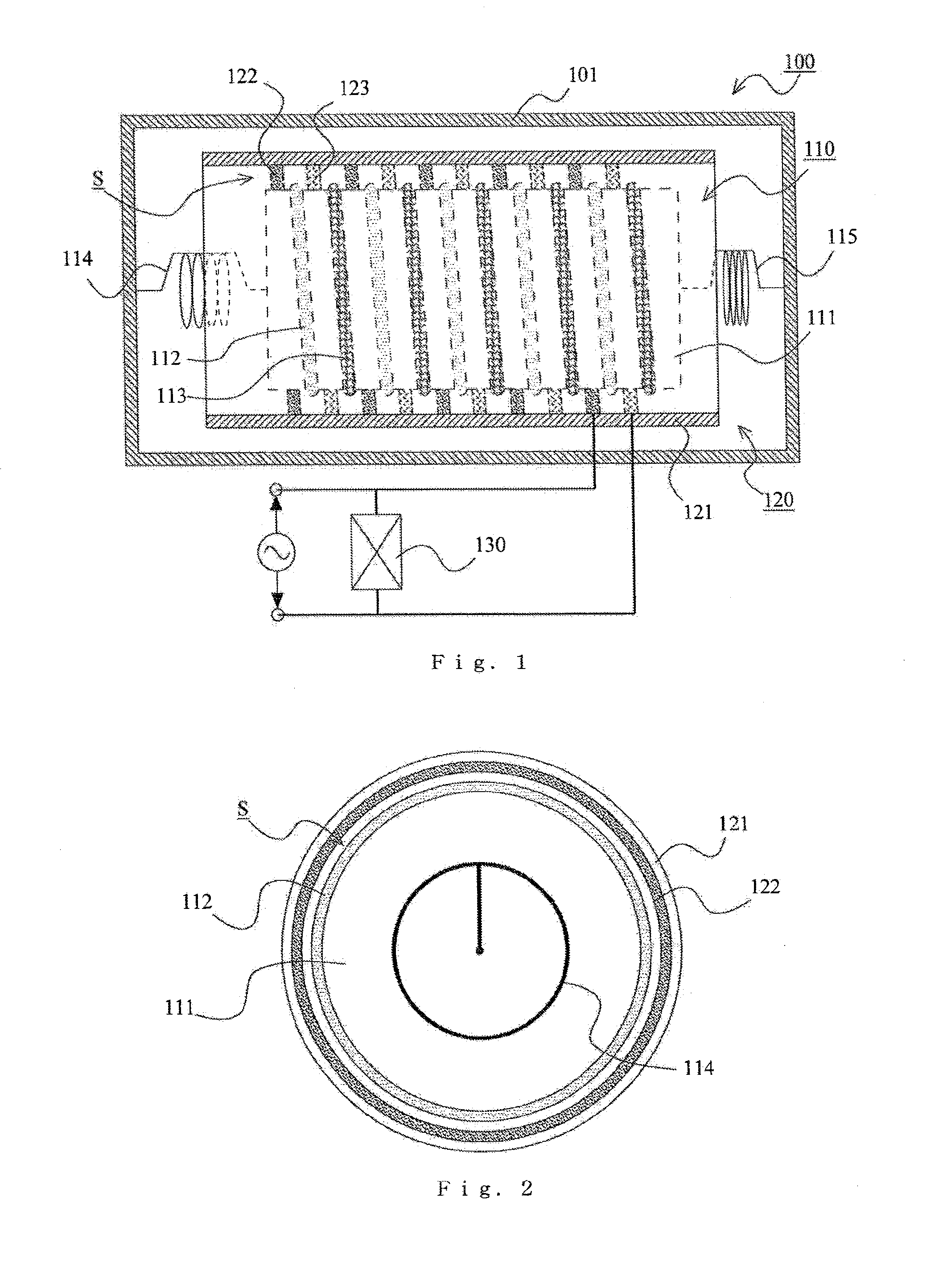
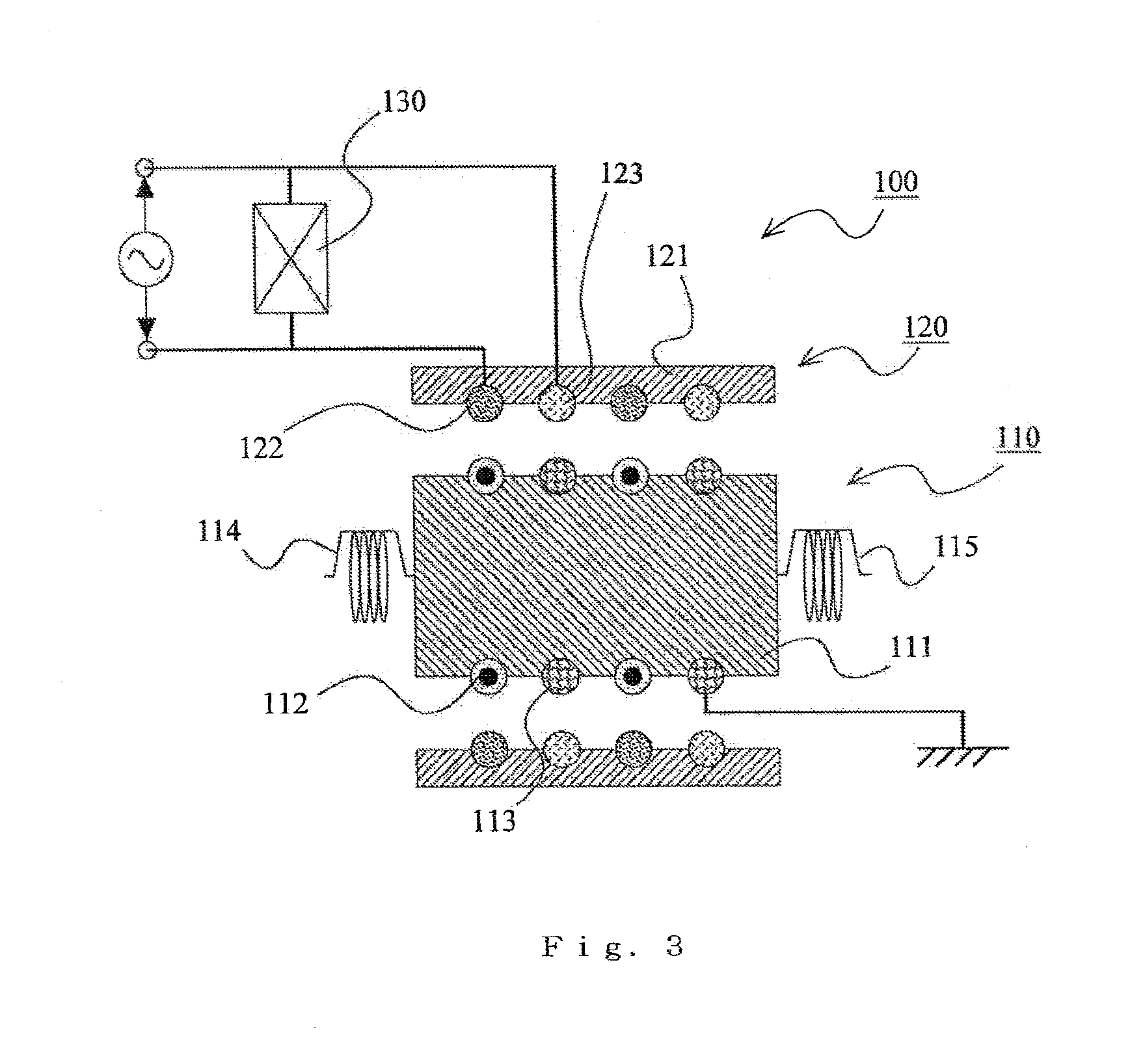
[0042]In particular, an overall configuration of the electrostatic induction power generator 100 according to Embodiment 1 of the present invention will be described with reference to FIGS. 1 to 3. FIG. 1 schematically shows the overall configuration. FIG. 2 is a diagram of major components (a first unit 110 and a second unit 120 excluding a housing 101) as seen from a side (from the left in the housing in FIG. 1). FIG. 3 is a schematic cross-sectional view (a cross-sectional view cut along a surface passing through the shaft center) of major components.

[0043]The electrostatic induction power generator 100 according to Embodiment 1 of the present invention includes the housing 101 and also includes the first unit 110 and the second unit 120 provided inside the housing 101.

[0044]The first unit 110 includes a first base body 111 formed of...

embodiment 2

[0060]FIG. 7 shows Embodiment 2 of the present invention. In Embodiment 1, a case is described in which a circular column shaped member is used as the first base body and a cylindrical member is used as the second base body. On the other hand, in the present embodiment, a case will be described in which a rectangular column shaped member is used as the first base body and a tube shaped member having rectangular cross sections of inner and outer circumferences is used as the second base body. The other components and functions are the same as those of Embodiment 1, so that the description of the same components will be omitted.

[0061]In an electrostatic induction power generator 200 according to the present embodiment, the first base body 211 is formed of a rectangular column shaped member. A cross-sectional shape of the rectangular column shaped member perpendicular to the reciprocating movement of the first base body 211 and the second base body 221 is a square. The second base body...

embodiment 3

[0065]FIG. 8 shows Embodiment 3 of the present invention. In the present embodiment, a case will be described in which a method of positioning the first electrode and the second electrode with respect to the second base body is different from that of Embodiment 1. The other components and functions are the same as those of Embodiment 1, so that the description of the same components will be omitted.

[0066]To improve power generation efficiency, it is necessary to improve positioning accuracy of the electret and the guard electrode with respect to the first base body and positioning accuracy of the first electrode and the second electrode with respect to the second base body. In Embodiment 1, a case is described in which grooves are provided on the base bodies and positioning is performed by fitting the electret and the like into the grooves.

[0067]Here, it is easy to attach the electret 112 and the guard electrode 113 to the outer circumference of the first base body 111 formed of a c...


PUM


Abstract

An electrostatic induction power generator includes a first base body and a second base body, which are configured to be able to reciprocate relative to each other and between which an annular clearance is formed. The electrostatic induction power generator further includes an electret provided on the first base body, and a first electrode and a second electrode provided on the second base body. The electret is formed by coating a charged dielectric material on a surface of a linear conducting wire and both of the first electrode and the second electrode are formed of a linear conducting wire.

Description

TECHNICAL FIELD[0001]The present invention relates to an electrostatic induction power generator that can be used as a vibration power generator or the like for generating power using ambient vibration.BACKGROUND ART[0002]Conventionally, an electrostatic induction power generator is known in which a pair of substrates configured to be able to reciprocate relative to each other while maintaining a state in which the substrates face each other are provided, a plurality of electrets are arranged in a row on one of the pair of substrates, and a plurality of pairs of electrodes are arranged in a row on the other one of the pair of substrates. According to the electrostatic induction power generator, when the pair of substrates move relative to each other, an electrostatic capacitance between one electrode of a pair of electrodes and the electret changes and also an electrostatic capacitance between the other electrode of a pair of electrodes and the electret changes, so that a difference...

Claims


Application Information

Patent Timeline
IPC IPC(8): H02N1/08
CPCH02N1/08H02N1/00H02N1/06
Inventor OKADA, WATARUSAKURAI, KENJI
Owner ORMON CORP
Why Eureka
Try Eureka