Display panel and gate driver therein

Active Publication Date: 2013-05-30
AU OPTRONICS CORP
View PDF7 Cites 28 Cited by
  • Summary
  • Abstract
  • Description
  • Claims
  • Application Information

AI Technical Summary

Benefits of technology

[0010]A gate driver of one embodiment comprises a plurality of cascade-connected driving stages. Each of the driving stages comprises a first shift register circuit and a second shift register circuit electrically coupled to the first shift register circuit. The first shift register circuit comprises a first input unit, a first drive output unit and a second drive output unit. The first input unit is configured for outputting a first control signal according to a previous stage driving signal. The first drive output unit is configured for outputting a present stage driving signal according to the first control signal and a first driving clock signal. The second drive output unit is configured for outputting a next stage driving signal according to the first control signal and a second driving clock signal. The second shift register circuit comprises a second input unit and a first output unit. The second input unit is configured for outputting a second control signal according to the previous stage driving signal. The first output unit is configured for outputting a present stage gate signal according to the second control signal and a first gate clock signal.
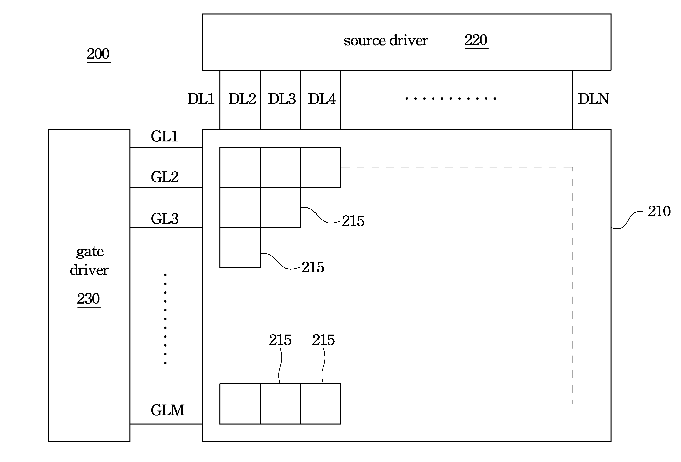
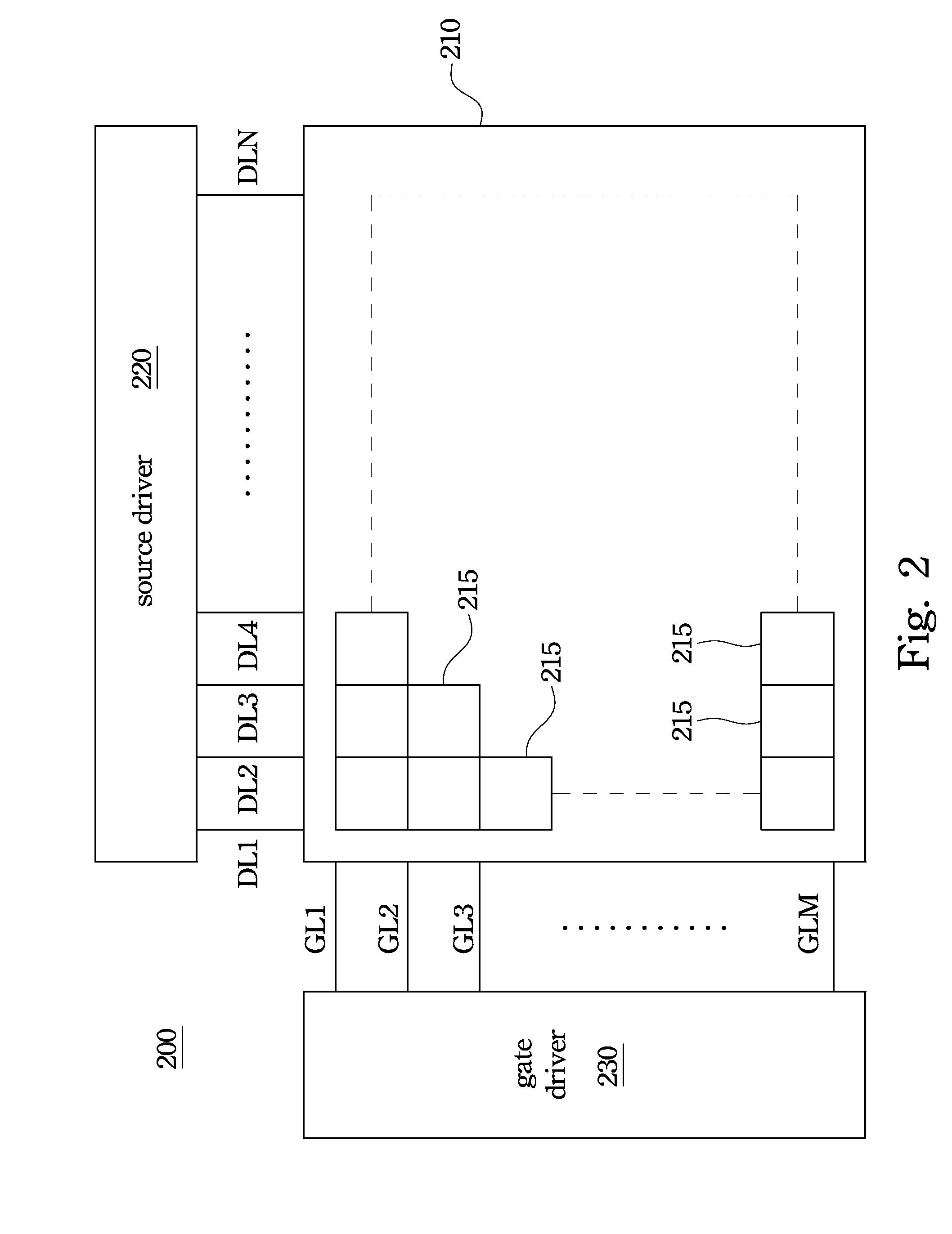
[0011]A display panel of one embodiment comprises a plurality of data lines, a plurality of gate lines interlacing with the data lines, and a gate driver. The gate driver is coupled to the gate lines and configured for outputting a plurality of gate signals sequentially to the gate lines, in which the gate driver comprises a plurality of cascade-connected driving stages, and each of the driving stages comprises a first input unit, a first switch, a second switch, a second input unit, a third switch, a first pull-down unit, and a second pull-down unit. The first input unit is configured for electrically c

Problems solved by technology

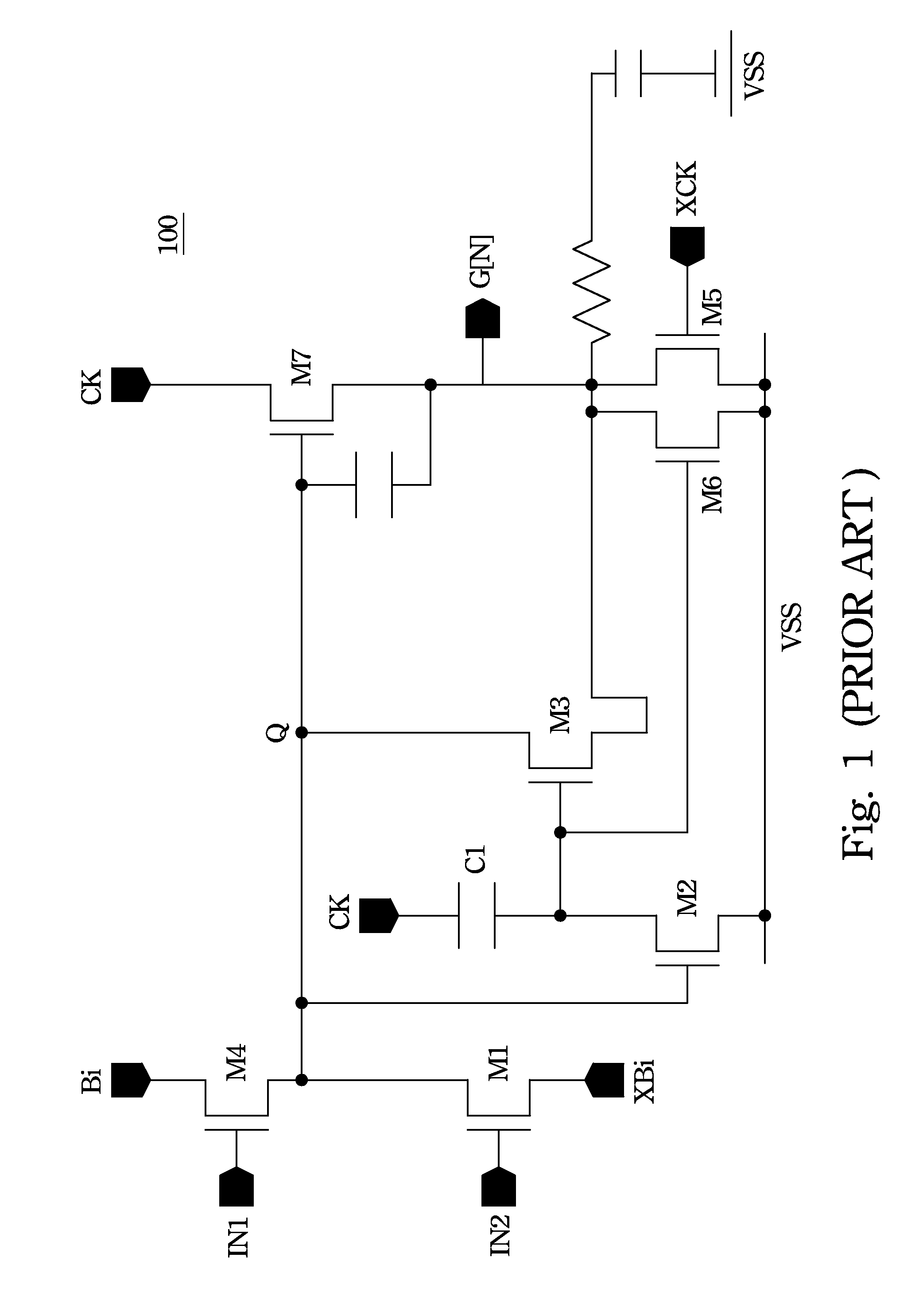
However, when the devices made of the material such as amorphous silicon or Indium-Gallium-Zinc Oxide are utilized in the gate driver circuit, the devices usually operate with leakage currents, and thus an output signal has ripples therein.
In other words, significant interference noises appear in the output signal and thus the power consumption increases.
Nonetheless, m

Method used


Image

  • Display panel and gate driver therein
  • Display panel and gate driver therein
  • Display panel and gate driver therein

Examples


Embodiment Construction

[0024]In the following description, specific details are presented to provide a thorough understanding of the embodiments of the present invention. Persons of ordinary skill in the relevant art will recognize, however, that the present invention can be practiced without one or more of the specific details, or in combination with other components. Well-known implementations or operations are not shown or described in detail to avoid obscuring aspects of various embodiments of the present invention.

[0025]The terms used in this specification generally have their ordinary meanings in the art and in the specific context where each term is used. The use of examples anywhere in this specification, including examples of any terms discussed herein, is illustrative only, and in no way limits the scope and meaning of the invention or of any exemplified term. Likewise, the present invention is not limited to various embodiments given in this specification.

[0026]As used herein, the terms “compri...


PUM


Abstract

A gate driver includes cascade-connected driving stages. Each of the driving stages includes a first shift register circuit and a second shift register circuit. The first shift register circuit is configured for outputting a present stage driving signal and a next stage driving signal. The second shift register circuit is electrically coupled to the first shift register circuit and configured for outputting a present stage gate signal, a first next stage gate signal, and a second next stage gate signal. Furthermore, a display panel is also provided herein.

Description

RELATED APPLICATIONS[0001]This application claims priority to Taiwan Patent Application Serial Number 100144053, filed Nov. 30, 2011, which is herein incorporated by reference.BACKGROUND[0002]1. Technical Field[0003]The present disclosure relates to a display panel. More particularly, the present disclosure relates to a gate driver in a display panel[0004]2. Description of Related Art[0005]In recent years, a liquid crystal display (LCD) has been commonly used as a display device because of its capability of displaying images with high quality while using little power consumption.[0006]For the LCD, a display panel of the LCD is driven by a driver circuit, and the driver circuit includes a gate driver circuit and a source driver circuit, in which the gate driver circuit generates gate signals sequentially transmitted on gate lines, thereby sequentially activating pixel units row by row, and the source driver circuit generates data signals transmitted through data lines to the pixel un...

Claims


Application Information

Patent Timeline
IPC IPC(8): G09G5/00
CPCG09G3/3674G11C19/28G09G2330/021G09G2310/0286
Inventor TSENG, CHIEN-CHANGLIU, KUANG-HSIANGTING, YU-HSINCHOU, SHIH-HSIANGCHANG, TING-JUI
Owner AU OPTRONICS CORP
Why Eureka
Try Eureka