Light-emitting diode road lamp structure

a technology of light-emitting diodes and road lamps, which is applied in the direction of fixed installation, lighting and heating equipment, lighting support devices, etc., can solve the problems of bringing about inferior heat-dissipation effect, lamp cannot be smoothly and freely convected, and heat-dissipation problems in the current, so as to reduce working temperature, improve heat-dissipation efficiency, and facilitate air flow

Inactive Publication Date: 2013-05-30
NAT APPLIED RES LAB
View PDF3 Cites 27 Cited by
  • Summary
  • Abstract
  • Description
  • Claims
  • Application Information

AI Technical Summary

Benefits of technology

[0026]First, the road lamp structure can smoothly guide the air flow and provide excellent heat-dissipation efficiency, thereby remaining the LED units at a lower working temperature to keep the luminous efficiency and extending the life span of the LED units. Further, because the LED units have excellent heat-dissipation efficiency, the LED road lamp can be designed in a closed type, thereby avoiding the rain or dust entering the inside of the LED road lamp to bring about the short circuits. Because the air flow can smoothly pass through the road lamp, the wind resistance of the road lamp can be reduced and the damages of the road lamp caused by the strong wind can be prevented. Further, with the rounded surface of the lamp tubes, the dust approaching the rounded lamp tubes can be quickly carried away by the air flow, thus to prevent the reduction of the lamp tubes caused by the accumulated dust. In addition, the optical luminance uniformity of the road lamp can be normally remained, and the heat-dissipation effect of the road lamp can be achieved without additional heat-dissipation device.

Problems solved by technology

However, in the process of electro-light conversion of the LED, there still has about 60% to 80% of electrical energy incapable of being converted into visible light, but this 60% to 80% of electrical energy is presented in the form of heat instead, this to bring about the heat dissipation problems in the current LED products.
However, in '917 case still has some technical issues required to be overcome as follows.
First, because the road lamp has a box-shaped device which is not streamlined and provides a large section therein, the fluid located on the top portion of the road lamp cannot be smoothly and freely convected, thus to bring about an inferior heat-dissipation effect.
Furthermore, because the road lamp is not a closed structure, the dust entering through the peripheral gas holes is easily accumulated on the heat-dissipation fins of the heat-dissipation elements, thus to bring about the reduction of the heat-dissipation efficiency of the heat-dissipation effect and short circuits caused by the introduced water.
Because the outline of the road lamp brings about a large wind resistance, the strong wind possibly damages the structure of the road lamp.
First, because the road lamp has a box-shaped device which is not streamlined and provides a large section therein, the fluid located on the top portion of the road lamp cannot be smoothly and freely convected, thus to bring about an inferior heat-dissipation effect.
Moreover, because the outline of the road lamp brings about a large wind resistance, the strong wind possibly damages the structure of the road lamp.
First, because the design of the heat-dissipation gas holes located at the bottom of the outer housing cannot provide a natural convection flow filed, the heat-dissipation effect of the LED road lamp is imperfect.
Furthermore, the water is easily to enter into the LED road lamp through the lateral gas holes, thus to bring about the inner circuit shorts.
Moreover, because the outline of the road lamp brings about a large wind resistance, the strong wind possibly damages the structure of the road lamp.

Method used


Image

  • Light-emitting diode road lamp structure
  • Light-emitting diode road lamp structure
  • Light-emitting diode road lamp structure

Examples


Embodiment Construction

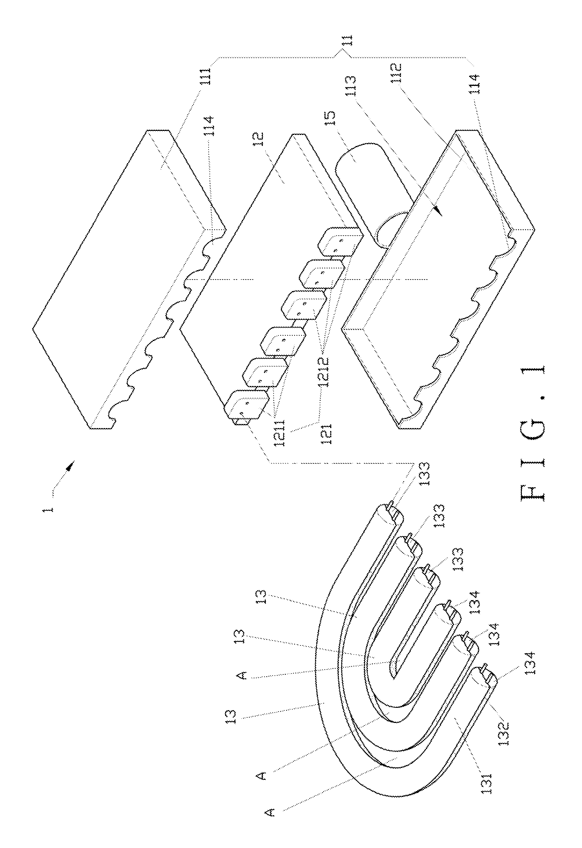
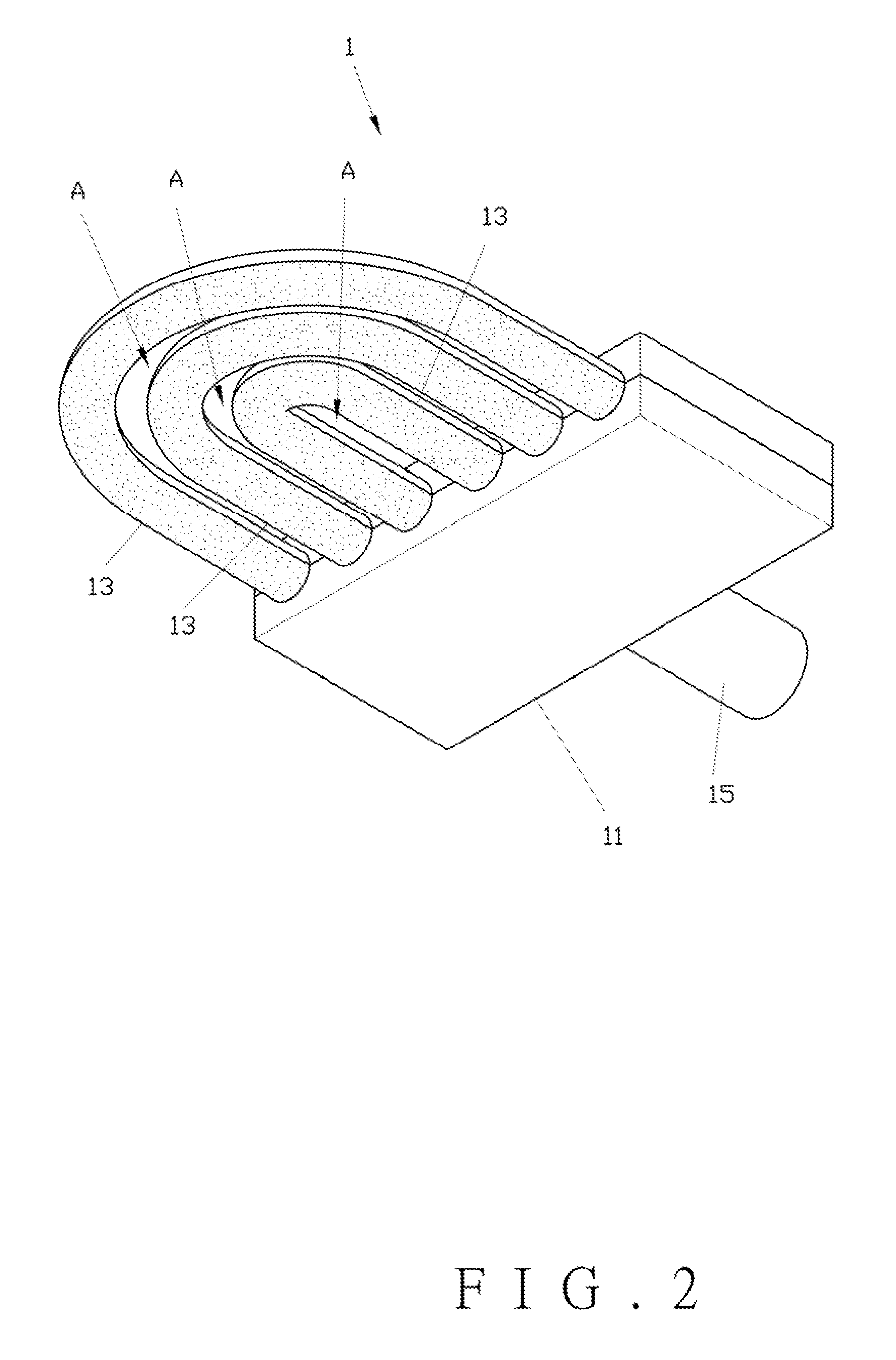
[0042]Referring to FIGS. 1 and 2, the light-emitting diode (LED) road lamp 1 according to a preferred embodiment of the present invention comprises a seat body 11, a circuit unit 12 and a plurality of light-emitting diode (LED) lamp tubes 13.

[0043]The seat body 11 comprises an upper seat body 111, a lower seat body 112 corresponding to the upper seat body 111, an accommodation space 113 defined between the upper seat body 111 and the lower seat body 112, and a plurality of openings 114 communicating with the accommodation space 113. A lamp-post head 15 is connected to one end of the seat body 11 opposite to the openings 114. The lamp-post head 15 is further connected to a lamp post (not shown in drawings).

[0044]The circuit unit 12 is a LED driving circuit component accommodated in the accommodation space 113. The circuit unit 12 comprises at least two sets of conductive terminals 121, and each set of which comprises a first electrode end 1211 and a second electrode end 1212. The fir...


PUM


Abstract

A light-emitting diode road lamp structure includes a seat body and a plurality of tube bodies. The seat body includes an accommodation space to accommodate a circuit unit. The tube bodies are juxtaposedly connected to an outside of the seat body, a plurality of light-emitting (LED) units accommodated in the tube bodies are electrically connected to the circuit unit, and an interspace is formed between each of the tube bodies and the tube body abutted therewith, thereby providing the road lamp with a better heat-dissipation efficiency by the air flow passing through the interspace, maintaining the luminous efficiency of the LED units, and extending the life span of the LED units.

Description

BACKGROUND OF THE INVENTION[0001]1. Field of the Invention[0002]The present invention relates to a light-emitting diode road lamp structure, and in particular relates to a road lamp structure providing light-emitting units dispersedly and juxtaposedly disposed outside a seat body and forming interspaces to allow the air flow passing there through to efficiently perform heat dissipation.[0003]2. Description of the Related Art[0004]In general, light-emitting diode (LED) lamp tubes are capable of conserving 60% to 70% of electricity without mercury vapor pollution, compared to fluorescent tubes. In view of the trend in the word on energy conservation and environmental protection issues, the fluorescent tubes are gradually replaced by the LED lamp tubes. However, in the process of electro-light conversion of the LED, there still has about 60% to 80% of electrical energy incapable of being converted into visible light, but this 60% to 80% of electrical energy is presented in the form of ...

Claims


Application Information

Patent Timeline
Patent Type & Authority Applications(United States)
IPC IPC(8): F21V1/00F21V21/00
CPCY02B20/72F21K9/175F21S8/086F21Y2101/02F21W2131/103F21Y2103/025F21V29/004F21V15/00F21Y2103/02F21K9/27F21Y2103/30F21Y2103/37F21Y2115/10F21V29/503F21V29/83
Inventor CHEN, CHIA-CHINLEE, JIUNN-HORNGFANG, YU-BINTSENG, TZU-IHSIAO, HUNG-TALIN, CHIN-FENG
Owner NAT APPLIED RES LAB
Why Eureka
Try Eureka