Facial expression control device

Inactive Publication Date: 2013-06-06
NAT TAIWAN UNIV OF SCI & TECH
View PDF30 Cites 1 Cited by
  • Summary
  • Abstract
  • Description
  • Claims
  • Application Information

AI Technical Summary

Benefits of technology

[0008]According to the currently known patents, references and products, it can be seen that, the robot head capable of facial expression generally has to use a large number of actuators to drive the controlling points of the facial skin to show variety facial expressions. And the m

Problems solved by technology

And the more actuators are used, the more facial expressions the robot head has, which

Method used


Image

  • Facial expression control device
  • Facial expression control device
  • Facial expression control device

Examples


first embodiment

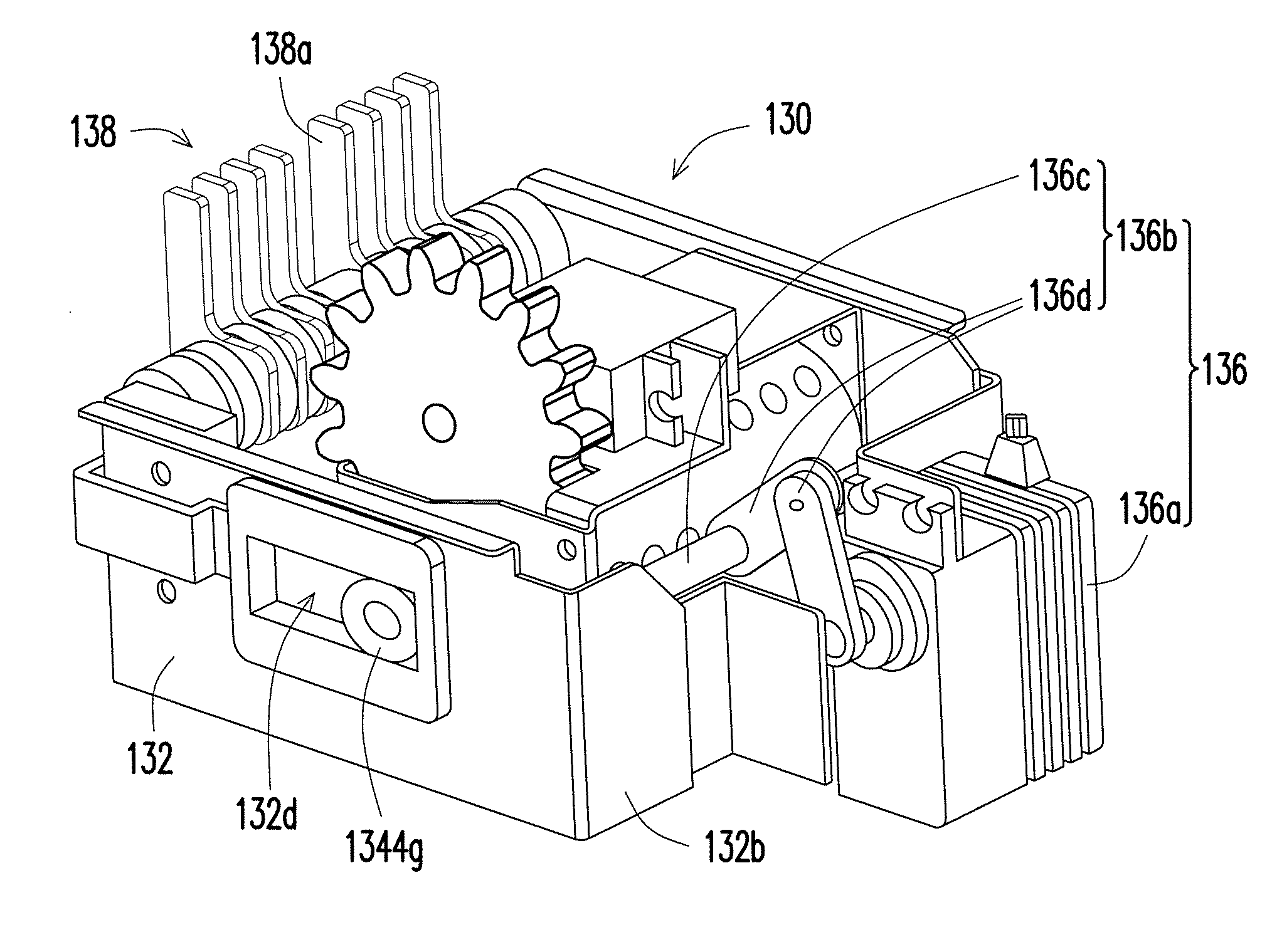
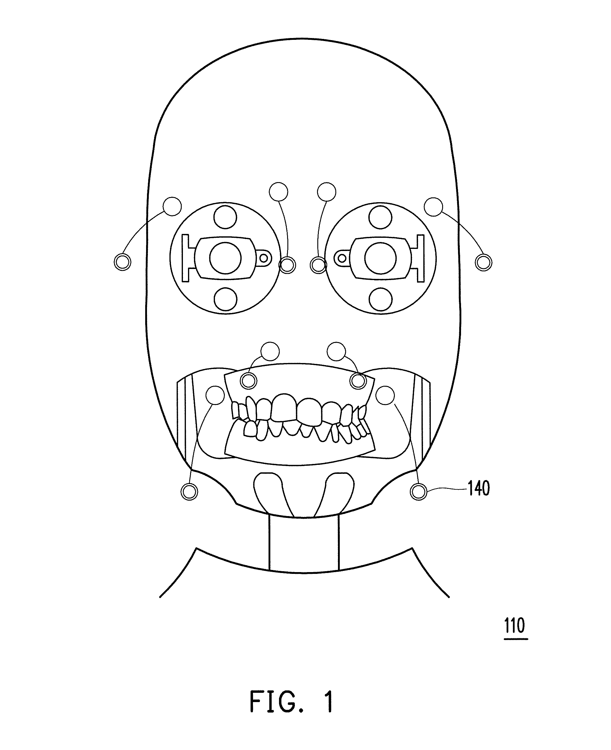
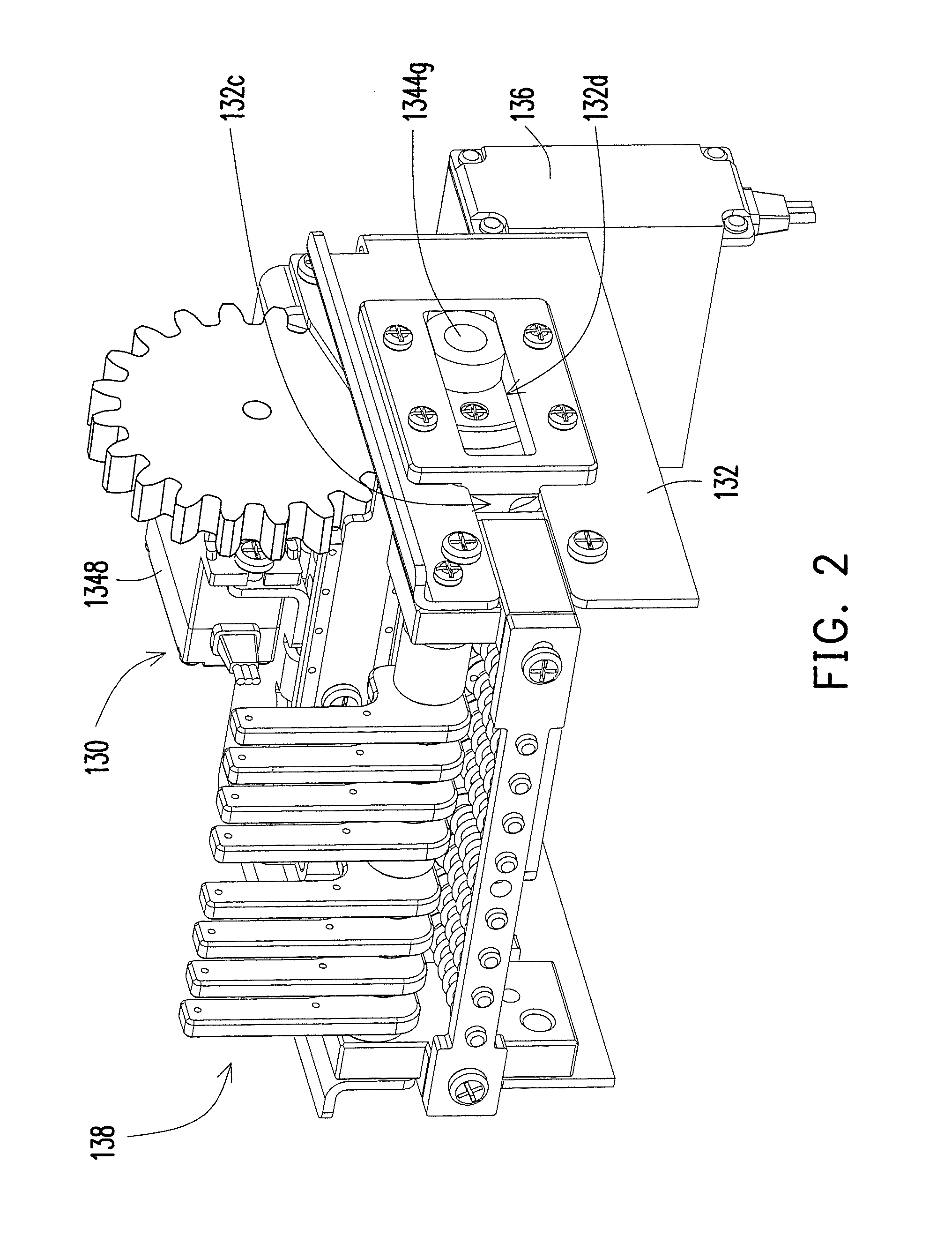
[0030]FIG. 1 is a schematic view of a facial skin of a robot head taken from the head of the robot. FIG. 2 is a schematic view of a facial expression control device disposed in the head. Referring to FIG. 1 and FIG. 2 together, the robot head includes a head 110, a facial skin (not shown), a facial expression control device 130, a main base 132 and a pushing assembly 136, wherein the head 110 has a cavity (not shown) used for placing the facial expression control device 130. The main base 132 is disposed in the cavity and the facial skin covers the head 110. The facial expression control device 130 is assembled to the main base 132 and connected with the facial skin. And the pushing assembly 136 is located relatively behind the head 110. The pushing assembly 136 pushes the facial expression control device 130 so as to pull the control points of the facial skin to make the robot head show facial expressions.

[0031]FIG. 3 is an exploded view of the facial expression control device of F...

second embodiment

[0047]FIG. 12 is a schematic view of the frame, the rotating element and the actuator of the second embodiment of the present invention. Referring to FIG. 3 and FIG. 12, though only one actuator 1348 is used to directly control one rotating element 1344 in the above mentioned embodiment, in order to increase the diversity of the facial expressions, one rotating element 2344 separated into two parts are used in this embodiment and other mechanical driving methods, for example, linkage, gear or combination thereof are used, so that one actuator 1348 can simultaneously drive the two rotating elements 2344, and the rotating directions of the two parts of the rotating element 2344 may be the same or opposite, and at the same time the rotating angles of the two parts of the rotating element 2344 can be the same or different. In this way, the facial expression control structures 2344b of the rotating elements 2344 can have much more combinations, and thus the robot head can have much more ...

third embodiment

[0048]In addition, though one row of the pushing bars and one row of the facial expression control structures are used in the description of the first embodiment, by this teaching people who have ordinary skill in the art may derive to other modifications according to the actual requirements. For instance, more rows of the pushing bars 1346 and more rows of the facial expression control structures 1344b can be disposed. FIG. 13 is a schematic view of the third embodiment of the present invention. Referring to FIG. 13, the rotating element 1344′ is a polyhedral prism. In FIG. 13, the included angle formed between any two adjacent edges 1344a′ and 1344a″ of the cross-sectional of the polyhedral prism are the same, and two rows of the facial expression structures 1344b′ can be disposed on each of the edges 1344a′ (or 1344a″). And the two pushing bars 1346 are respectively inserted into the two rows of the facial expression control structures 1344b′ of the rotating element 1344′. Corres...


PUM


Abstract

A facial expression control device is provided. The facial expression control device of the present invention provides multiple structures and links, wherein the links are connected to the linking assembly; therefore varies facial expressions are expressed according to the combination of the structures and links. In this way, the facial expression is changed by means of the least actuators under the condition of maintaining the number of facial expression and imitation.

Description

CROSS-REFERENCE TO RELATED APPLICATION[0001]This application claims the priority benefit of Taiwan application serial no. 100144852, filed on Dec. 6, 2011. The entirety of the above-mentioned patent application is hereby incorporated by reference herein and made a part of this specification.BACKGROUND OF THE INVENTION[0002]1. Field of the Invention[0003]The present invention is related to a control device and a robot using the control device, and more particularly, is related to a facial expression control device and a robot head using the facial expression control device.[0004]2. Description of Related Art[0005]The technique of emulation robot head having a humanoid appearance is proposed by Hara and Kobayashi of Tokyo Institute of Technology. They used pneumatic actuators to control the artificial facial skin fabricated by the silicone rubber. The artificial facial skin is provided with softness and flexibility, and thus the facial skin can express six basic facial expressions (su...

Claims


Application Information

Patent Timeline
IPC IPC(8): G05G9/00
CPCA63H13/005Y10T74/20012A63H3/20
Inventor LIN, CHYI-YEUHUANG, CHUN-CHIA
Owner NAT TAIWAN UNIV OF SCI & TECH
Why Eureka
Try Eureka