Integrated optical transducer and method for fabricating an integrated optical transducer

a technology of optical transducers and integrated optical transducers, which is applied in the direction of electrical transducers, loudspeakers, instruments, etc., can solve the problems of affecting the effective back volume, reducing the size of components, complicated fabrication processes, etc., and achieves reduced size and high sensitivity

Active Publication Date: 2021-12-23
AMS AG
View PDF2 Cites 0 Cited by
  • Summary
  • Abstract
  • Description
  • Claims
  • Application Information

AI Technical Summary

Benefits of technology

[0004]This disclosure provides an improved concept for an integrated optical transducer with reduced size and high sensitivity.
[0008]For such an integrated transducer, the MEMS die and the ASIC die are enabled to be fabricated separately, such that no costly and complicated fabrication process is required that is both MEMS and CMOS compatible at the same time. Instead, the MEMS die is fabricated following a MEMS compatible process for forming the suspension structure and the MEMS diaphragm, which is for example a membrane made of a material such as silicon nitride, crystalline-silicon or poly-silicon. Independent from this, the ASIC die is fabricated following a CMOS compatible process for forming the ASIC, which comprises the evaluation circuit for reading out a deflection of the MEMS diaphragm induced by dynamic pressure changes, such as acoustic pressure waves.
[0012]Conventional transducers, for example those based on an optical interferometric grating or on a capacitive readout, typically require an element that is arranged in between the evaluation circuit and the diaphragm, for example a perforated back plate or a back plate acting as electrode, close to the diaphragm, which can influence the effective back volume and / or make the fabrication process more complicated. Typically, this means that either an additional third die is required in order to provide this additional element, or this element is fabricated on the MEMS die, making its fabrication process more elaborate and costly.
[0014]In contrast, a transducer according to the improved concept utilizing the described readout method only consists of the MEMS die and the ASIC die as its only dies. This implies a compact design without an enlarging enclosure package as well as a short and simple fabrication routine.
[0016]Stress release structures may be used for preventing a large amount of stress induced onto the MEMS die, for example during handling and operation of the finalized transducer but also at an earlier stage during bonding of the MEMS die to the ASIC die. For instance, a dedicated adhesive, a patterned adhesive or gold bumps may be employed as stress release structures on the MEMS die and / or on the ASIC die. With this, also an attachment, or bonding, of the transducer to a printed circuit board, PCB, may be performed without risking breakage of the transducer and / or its components.
[0019]In contrast, the above-mentioned optical readout permits gap heights in excess of 20 μm or even 100 μm or 200 μm, therefore significantly increasing the enclosed back volume and hence providing a large acoustic capacitance. As a consequence, an air compression caused by a deflection of the diaphragm towards the ASIC die, for example caused by an incident pressure wave, is distributed across the entire back volume and therefore provides less acoustic impedance that destructively acts back onto the diaphragm. Limitations of conventional transducers are consequently overcome in these embodiments without the requirement of an additional package, therefore enabling high-sensitivity transducers in a compact design.

Problems solved by technology

Due to increasing space constraints of these devices, components are becoming more and more compact and are decreasing in size.
Conventional transducers, for example those based on an optical interferometric grating or on a capacitive readout, typically require an element that is arranged in between the evaluation circuit and the diaphragm, for example a perforated back plate or a back plate acting as electrode, close to the diaphragm, which can influence the effective back volume and / or make the fabrication process more complicated.
Typically, this means that either an additional third die is required in order to provide this additional element, or this element is fabricated on the MEMS die, making its fabrication process more elaborate and costly.
Conventional transducers based on capacitive readout typically have the limitation of a small gap between the diaphragm and the electrode back plate with a gap height of less than 5 μm.
However, the small gap in these conventional transducers comes at the expense of a large acoustic impedance, which is caused by the limited compressibility of the air in combination with the small acoustic capacitance of the air inside the small back volume.
For other applications, this electrical connection may either not be desirable or required such that no additional via is necessary.

Method used


Image

  • Integrated optical transducer and method for fabricating an integrated optical transducer
  • Integrated optical transducer and method for fabricating an integrated optical transducer
  • Integrated optical transducer and method for fabricating an integrated optical transducer

Examples


Embodiment Construction

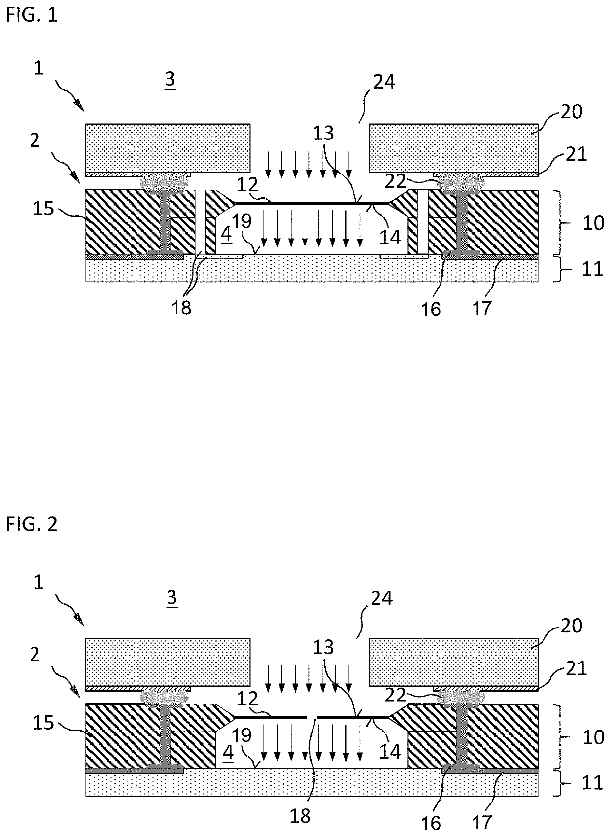
[0048]FIG. 1 shows a cross section view of a microphone assembly 1 that comprises an integrated optical transducer 2 according to the improved concept. In particular, the microphone assembly 1 shown comprises an integrated optical transducer 2 which is electrically and mechanically connected to contact pads 21 of a printed circuit board, PCB, 20.

[0049]The integrated optical transducer 2 comprises a micro-electro-mechanical systems, MEMS, die 10 as a first die and an application-specific integrated circuit, ASIC, die 11 as a second die. The MEMS die 10 is in fused contact with the ASIC die 11, for example the two dies 10, 11 are bonded via conventional wafer bonding techniques which may be of an adhesive or of a eutectic type. The two dies 10, 11 may be the only dies of the integrated optical transducer 2.

[0050]The MEMS die 10 comprises a MEMS diaphragm 12, which may be a suspended membrane made of a crystalline or polycrystalline material such as silicon or poly-silicon, a dielectri...


PUM

PropertyMeasurementUnit
gap heightaaaaaaaaaa

Abstract

An integrated optical transducer for detecting dynamic pressure changes comprises a micro-electro-mechanical system, MEMS, die having a MEMS diaphragm with a first side exposed to the dynamic pressure changes and a second side. The transducer further comprises an application specific integrated circuit, ASIC, die having an evaluation circuit configured to detect a deflection of the MEMS diaphragm, in particular of the second side of the MEMS diaphragm. The MEMS die is arranged with respect to the ASIC die such that a gap with a gap height is formed between the second side of the diaphragm and a first surface of the ASIC die and the MEMS diaphragm, the ASIC die and a suspension structure of the MEMS die delineate a back volume of the integrated optical transducer.

Description

CROSS-REFERENCE TO RELATED APPLICATIONS[0001]The present application is the national stage entry of International Patent Application No. PCT / EP2019 / 072608, filed on Aug. 23, 2019, published as WO 2020 / 064239 A1 on Apr. 2, 2020, which claims benefit of priority of European Patent Application No. 18196907.2 filed on Sep. 26, 2018, all of which are hereby incorporated by reference in their entirety for all purposes.FIELD OF THE INVENTION[0002]This disclosure relates to an integrated optical transducer for sensing dynamic pressure changes, in particular acoustic waves, and to a fabrication method of such a transducer.BACKGROUND OF THE INVENTION[0003]Micro-electro-mechanical systems, MEMS, transducers for sensing dynamic pressure changes are used in a wide range of applications in modern consumer electronics, in particular as microphones for sensing pressure waves in the acoustic frequency band. Common examples in which integrated MEMS microphones play an important role are portable comp...

Claims


Application Information

Patent Timeline
Patent Type & Authority Applications(United States)
IPC IPC(8): H04R23/00G01H9/00
CPCH04R23/008H04R2201/003G01H9/00G01H11/00H04R2201/00H04R2499/15
Inventor STOJANOVIC, GORANSTEELE, COLINLOUS, ERIK JANPIRES SINGULANI, ANDERSON
Owner AMS AG
Why Eureka
Try Eureka