Squeegee Blade For Screen Printing And Methods Of Manufacture And Use Of Same

a technology of screen printing and squeegee blades, which is applied in the field of improved squeegee blades, can solve the problems of reducing print quality, excessive interface area between ink piles, dot gain, or mottling, and achieves high-speed print runs without excessive screen ripping, and reduces downward pressur

Inactive Publication Date: 2013-06-06
CLARKE JOE
View PDF6 Cites 9 Cited by
  • Summary
  • Abstract
  • Description
  • Claims
  • Application Information

AI Technical Summary

Benefits of technology

[0008]In another preferred aspect of the invention, the improved squeegee blade is formed from a di-isocyanate polyurethane resin with a Shore A hardness of greater than about 65. In one preferred embodiment of the invention, the improved squeegee blade is molded from Methylene di-isocyanate resin which has a Shore A hardness of about 85. The provision of a buckle control channel is believed to allow the improved squeegee blades of the present invention to be formed from significantly harder materials than would otherwise be feasible to utilize for efficient screen printing. With prior art blade designs, blade manufactured with resins having a Shore A hardness of greater than about 65 typically have lead to unacceptable high screen rip rates and / or less than desirable print quality due to blade hinging during print runs. For this reason, they have been generally avoided in favor of blades having a Shore A hardness of between 45 and 60. Accordingly, it is one object of the present invention to provide improved blades squeegee designs that can be made from significantly harder materials than have hereto been feasible for efficient screen printing. It has been found that the blades of the present invention can produce high quality, high speed print runs without excessive screen ripping.
[0009]The present inventor has further discovered that the improved squeegee blade designs of the invention can allow a screen printing press to be set up with significantly lower downward pressure on the squeegee blade, which allows the press to operate at significantly higher print speeds. Those lower downward pressure parameters also provide the benefit of decreasing wear on the squeegee blade, the screen mesh, stencil (if one is called for in a particular print job) and other screen printing press components. Accordingly, in accordance with another aspect of the invention, an improved method of screen printing is provided including the steps of: providing a screen printing press which includes an improved squeegee blade having a buckle control channel formed in one of the front face and the back surface of the blade; setting the printing press to provide a downward squeegee blade pressure of less than about 40 N / cm2, loading a substrate and ink into the screen printing press, spreading ink onto the screen above the substrate, and causing the ink to be printed onto the substrate by moving the squeegee blade across the screen in contact with the spread ink and screen mesh thereby forcing the ink through the mesh and onto the substrate. In one preferred method of the invention, the process of setting up the printing press includes the further step of setting the initial blade angle on the improved squeegee blade such that the blade face is substantially perpendicular to the screen of the printing press. In another aspect of the methods of the invention, the initial blade angle of the improved squeegee blade is set such that the blade face is positioned to be less than about 7 degrees from perpendicular with the printing press screen, and preferably between 3 and 5 degrees from perpendicular. In another aspect of the methods of the invention, the printing press is set up to print with a squeegee blade speeds of greater than 10 (ten) inches per second and preferably from 15 to 25 inches per second to print on a clothing substrate, such as a T-shirt. In another aspect of the methods of the invention, the squeegee blade buckles along the length of channel in a manner which maintains a substantially linear printing edge on the squeegee blade along its length in the in the print stroke axis (y-axis) throughout a print stroke.

Problems solved by technology

Such hinging greatly reduces print quality.
Soft conventional blades, on the other hand, typically hinge in an uncontrolled manner result in excess interface area between the mesh and blade, which can cause ink piling, dot gain, or mottling.
While it is theoretically possible to print material on a screen press that has a screen that is far larger than the substrate upon which ink is to be printed, in the real world of commercial printing, this infrequently occurs.
With prior art blade designs, blade manufactured with resins having a Shore A hardness of greater than about 65 typically have lead to unacceptable high screen rip rates and / or less than desirable print quality due to blade hinging during print runs.

Method used


Image

  • Squeegee Blade For Screen Printing And Methods Of Manufacture And Use Of Same
  • Squeegee Blade For Screen Printing And Methods Of Manufacture And Use Of Same
  • Squeegee Blade For Screen Printing And Methods Of Manufacture And Use Of Same

Examples


Embodiment Construction

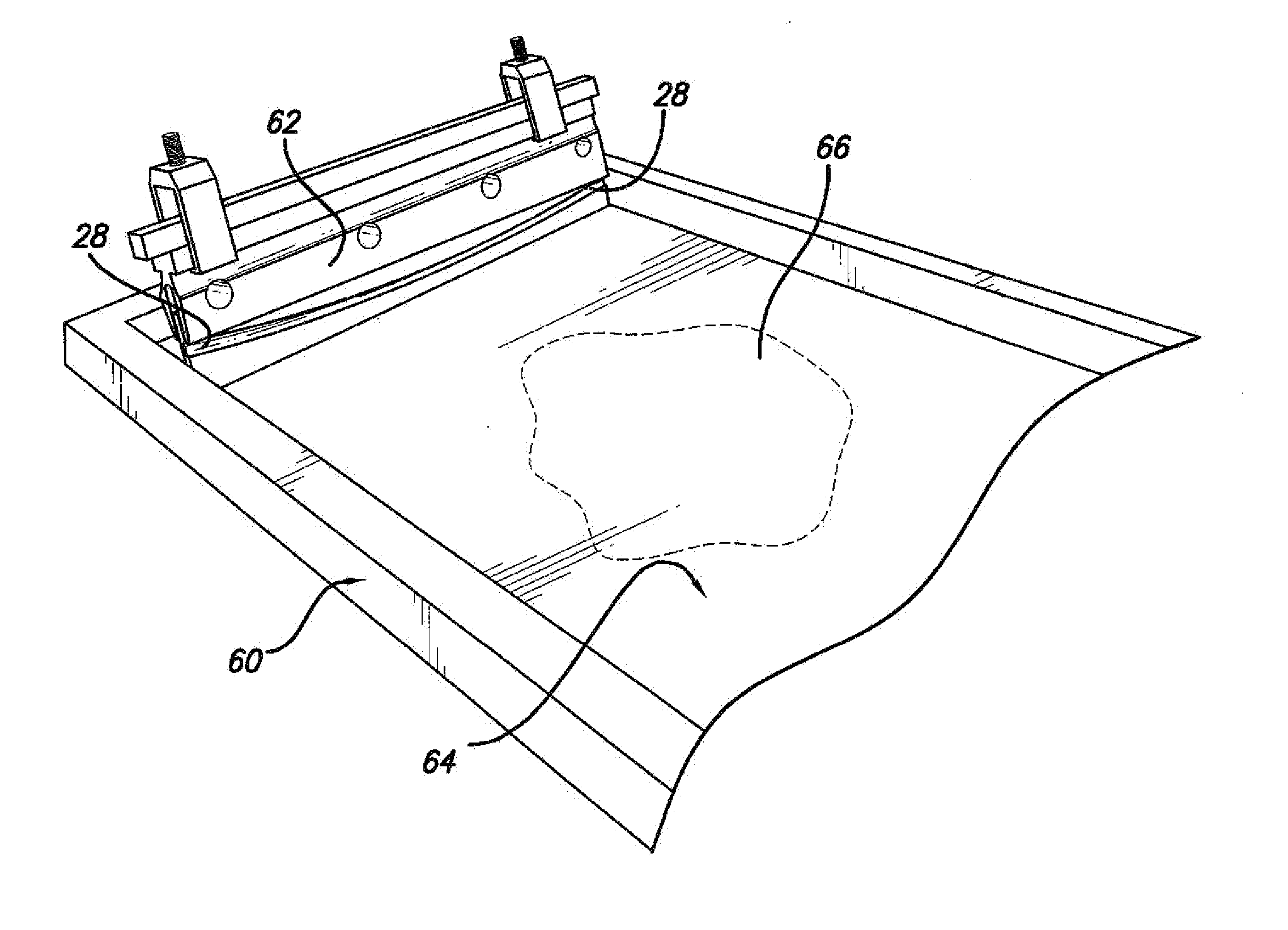
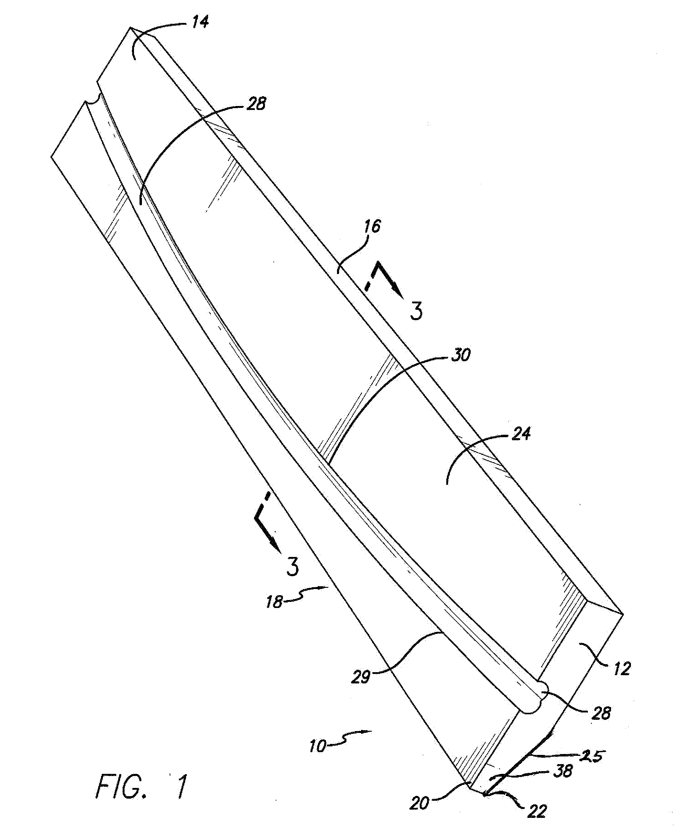
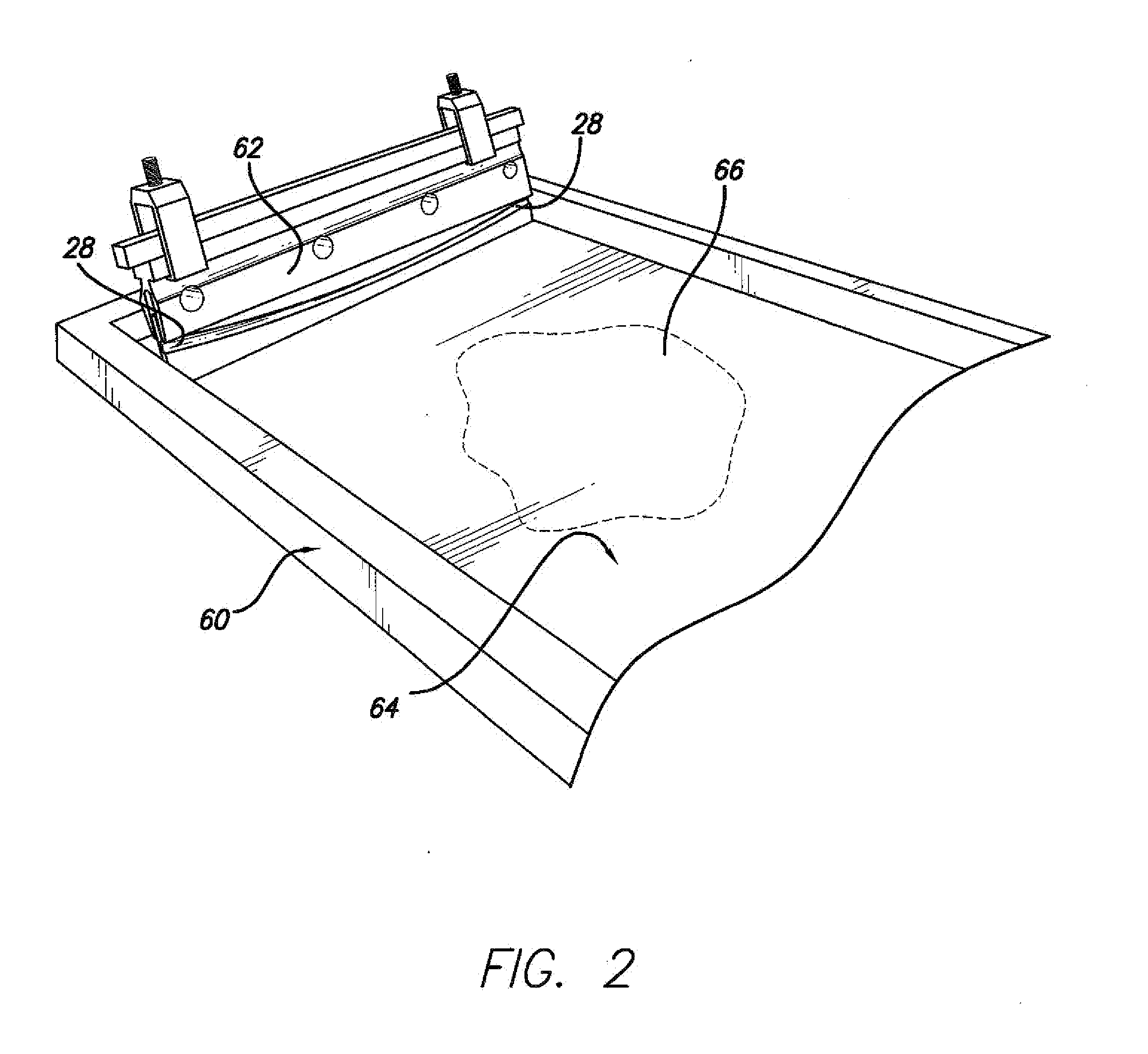
[0025]As illustrated in FIGS. 1-6, a first embodiment of an improved squeegee blade 10 of the invention is provided, which includes, a first end 12, a second end 14, a top surface 16 for receipt by a blade holder 62, a bottom surface 18, a front face 24, and a back surface 26, a first printing edge 20 joining the front face 24 and bottom surface 18, a second print edge 22 joining the bottom surface 18 and back surface 26, bull nose corner portions at the ends of the bottom surface 18, and a buckle control channel 28 formed in the front face 24. Both printing edges 20 and 22 are adapted for contacting the screen 64 of a screen printing press 60 (see FIG. 2). The squeegee blade 10 is generally an elongated rectangular in shape with the exception of the beveled surface 25 printing edge 22, bull nose corner portions 38, and the buckle control channel 28.

[0026]Turning to the details of the squeegee blade 10, blades of this design have proven to significantly increase the efficiency of th...


PUM


Abstract

The present invention is directed to improved screen printing squeegee blades, which include a first end, a second end, a top portion for receipt by a blade holder, a bottom portion adapted for contacting the screen of a screen printing press along at least one printing edge, a front face, a back surface, and a buckle control channel formed in either the front face or the back surface.

Description

FIELD OF THE INVENTION[0001]The present invention is directed to improved squeegee blades for use in commercial screen printing presses, as well as methods for manufacturing such blades and printing with such blades. More particularly, the invention is directed to a squeegee blade which includes a buckle control channel formed in the blade to provide consistent, regulated squeegee blade buckling along the blade length, as well as methods of manufacturing and processes for printing utilizing such improved blades.BACKGROUND OF THE INVENTION[0002]There are currently a variety of squeegee blades utilized in screen printing presses to induce ink to travel through a mesh screen onto a substrate to receive the ink. Conventional squeegee blades have proven to be less than adequate when utilized under conventional press set up parameters, which typically include relatively high downward force on the blade holder and less than optimal blade speeds for a given ink and printed image size. When ...

Claims


Application Information

Patent Timeline
Patent Type & Authority Applications(United States)
IPC IPC(8): B41F15/44
CPCB41F15/44
Inventor CLARKE, JOE
Owner CLARKE JOE
Why Eureka
Try Eureka