
Sound-based damage detection

a sound-based damage detection and sound technology, applied in the field of sound-based damage detection, to achieve the effect of saving cost and occupying spa

Inactive Publication Date: 2013-06-06
EASTMAN KODAK CO
View PDF2 Cites 44 Cited by
  • Summary
  • Abstract
  • Description
  • Claims
  • Application Information

AI Technical Summary

Benefits of technology

The invention is for a sound-based damage detection system that only requires one microphone. This saves cost and allows for placement in tight spaces. The microphone is mounted in a compliant mount to reduce unwanted sounds and vibrations. The sound data collected by the microphone is processed to determine misfeeds or damage to the article processing apparatus. This is done by collecting data frames and calculating the energy levels of the data frames. A jam count window is opened if the energy level exceeds a threshold. If the jam count reaches a certain level, a jam signal is generated. The jam count window is closed if the jam count reaches a certain level and the jam count is reset to zero.

Problems solved by technology

Incorporating multiple devices for receiving audio information (typically in the range of 1 KHz. to 10 KHz.) represents both a cost penalty and a packaging challenge given the position of drive rollers and other sensors within the document transport design.

Method used


Image

  • Sound-based damage detection
  • Sound-based damage detection
  • Sound-based damage detection

Examples


Embodiment Construction

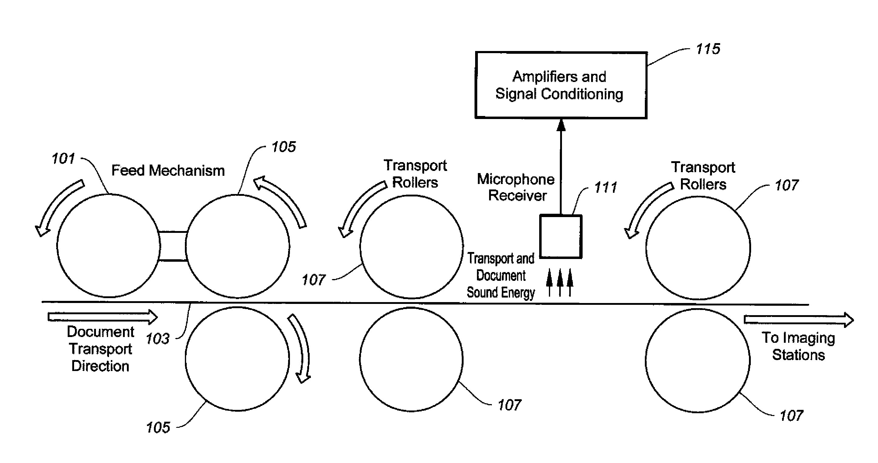
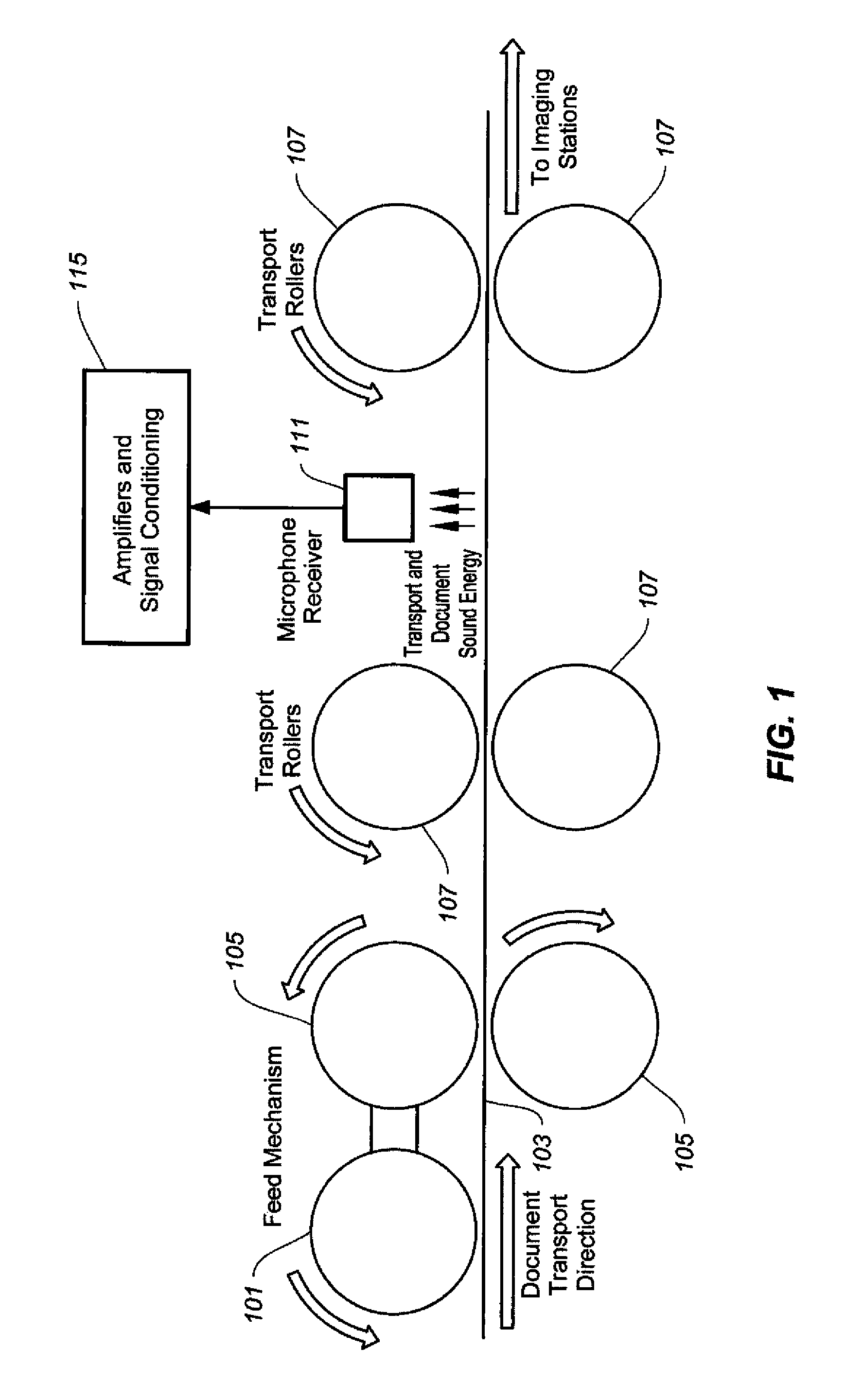
[0024]With reference to FIG. 1, document 103 is moved forward by urging roller 101 into the feed and separation nip created by contact of rollers 105. Not shown is a standard input tray holding a stack of documents wherein the urging roller is configured to separate the first one of the documents from the stack. One document at a time is sequentially pushed further into the transport rollers 107 by selective rotation of the feed mechanism rollers 105. Ultimately the document is transported to an imaging station or stations to be converted into a digital image. Sound energy created by the physical transport of the document through the transport is also converted to an electrical signal by receiver 111. This sound energy may be characteristic of normal, undamaged transport of the document including that of the scanner itself, or may contain sounds characteristic of a document undergoing damage as a result of the feed and / or transport process. The electrical signal from microphone 111 ...


PUM


Abstract

A document handling apparatus having a document transport path for moving a document therethrough. A single detector proximate the transport detects a misfeed indication in the transport path. A processing system processes the indication and issues a termination signal if a misfeed is determined.

Description

CROSS REFERENCE TO RELATED APPLICATIONS[0001]The following U.S. patent applications are assigned to the same assignee hereof, Eastman Kodak Company of Rochester, N.Y., and contain subject matter related, in certain respect, to the subject matter of the present patent application. These patent applications are incorporated herein by reference in their entirety.[0002]U.S. Ser. No. 13 / 273,263, filed Oct. 14, 2011, entitled “Jam Sensing At Document Feeding Station”;[0003]US patent application filed concurrently herewith, entitled “Combined Ultrasonic-Based Multifeed Detection Method And Sound-Based Damage Detection Method”, and[0004]US patent application filed concurrently herewith, entitled “Combined Ultrasonic-Based Multifeed Detection System And Sound-Based Damage Detection System”.FIELD OF THE INVENTION[0005]The present invention is directed to devices and methods of detecting misfeeds in a document handling apparatus. In particular, to devices and methods utilizing only one detecto...

Claims


Application Information

Patent Timeline
IPC IPC(8): B65H7/06
CPCB65H5/062B65H7/06B65H2511/51B65H2511/52B65H2511/528B65H2513/512B65H2553/30G03G15/607G03G15/6558G03G15/70H04N1/00013H04N1/00034H04N1/0005H04N1/00058H04N1/00074H04N1/0057B65H2220/03B65H2220/02B65H2220/01
Inventor PHINNEY, DANIEL P.MAYSICK, RANDALL R.MIDDLETON, THOMAS GREGORYSAKHARSHETE, SWAPNILSCHAERTEL, DAVID M.SYRACUSE, ANTHONY A.
Owner EASTMAN KODAK CO
Learn More