Actuator, robot hand, robot, electronic component carrying device, electronic component inspection device, and printer

a technology of electronic components and printers, which is applied in the direction of generators/motors, manufacturing tools, hoisting equipment, etc., can solve the problems of considerable leakage of the piezoelectric body, and loss of driving energy of the driven body, so as to shorten the operating time of the printer and achieve high productivity , the effect of high speed

Inactive Publication Date: 2013-06-06
SEIKO EPSON CORP
View PDF6 Cites 17 Cited by
  • Summary
  • Abstract
  • Description
  • Claims
  • Application Information

AI Technical Summary

Benefits of technology

[0006]An advantage of some aspects of embodiments of the invention is to provide an actuator that suppresses vibration leakage of a piezoelectric body to a holding case while holding the piezoelectric body by the holding case, and to reliably convert vibration of the piezoelectric body into vibration of a driven body.
[0033]According to the printer according to this application example, since the actuator with high driving resolution and high speed vibration is included in the driving device unit, it is possible to reliably move a driving object to an objective position with high speed, to shorten operating time of the printer, and to realize high productivity. In addition, since the driving is performed with high speed, it is possible that a driving of a cutter which performs long linear driving and cuts a printing medium is smoothly performed.

Problems solved by technology

However, in Pamphlets of International Publication WO 2007 / 80851 and WO 2008 / 93799, since the elastic member which holds the piezoelectric body is disposed so as to limit a vibration in a vibration direction of the piezoelectric body, particularly with respect to a bending vibration, there is a concern that the vibration of the piezoelectric body is leaked to the holding case through the elastic member and a considerable amount of driving energy of the driven body is lost.
In JP-A-2007-189900, there is a concern that vibration leakage is generated from a guide unit of the holding case which holds the piezoelectric body and a considerable amount of driving energy of the driven body is lost.

Method used


Image

  • Actuator, robot hand, robot, electronic component carrying device, electronic component inspection device, and printer
  • Actuator, robot hand, robot, electronic component carrying device, electronic component inspection device, and printer
  • Actuator, robot hand, robot, electronic component carrying device, electronic component inspection device, and printer

Examples


first embodiment

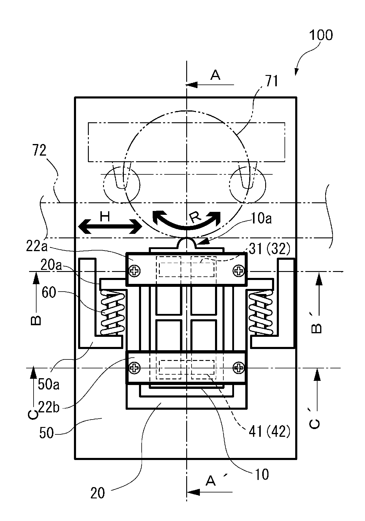
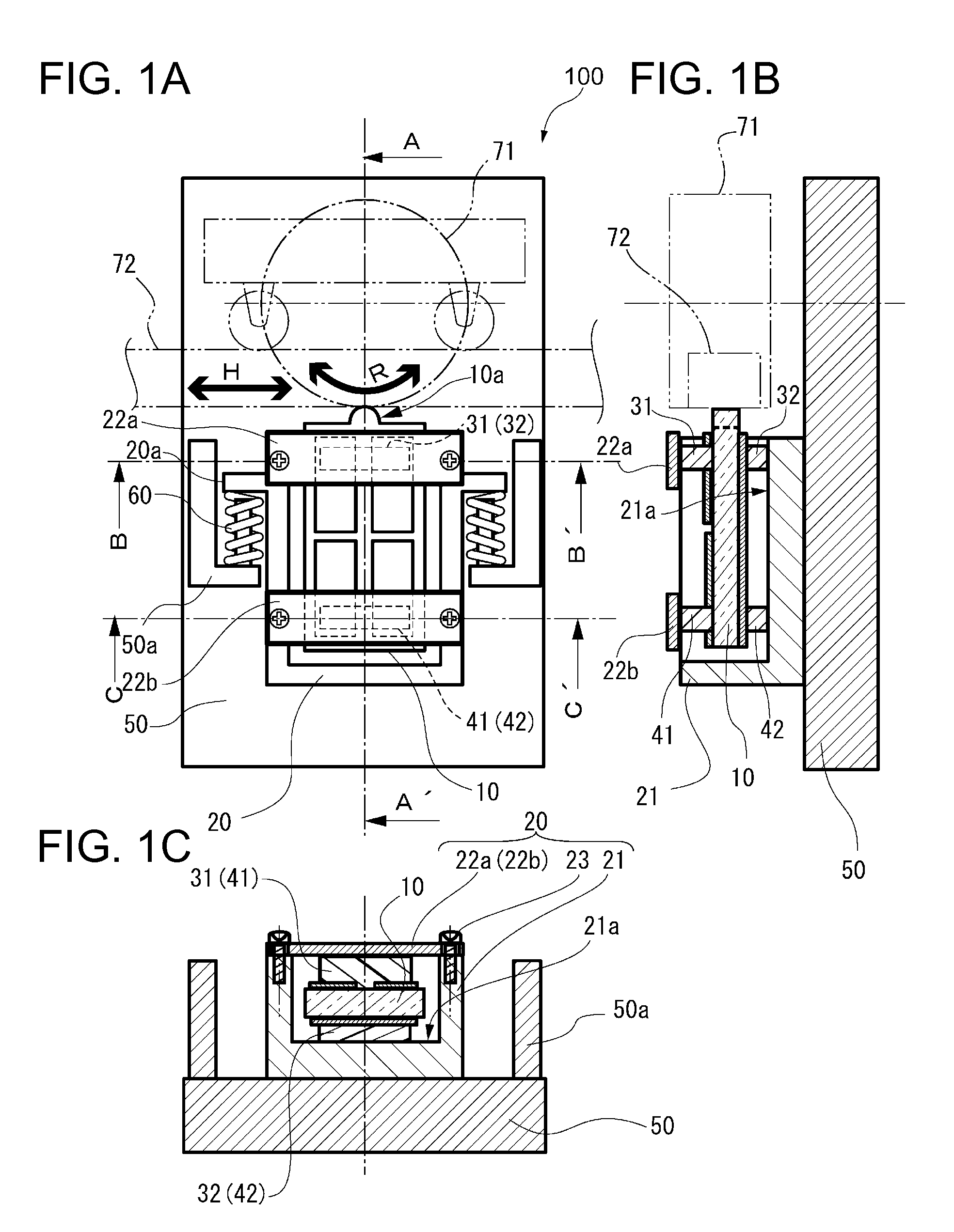
[0049]FIG. 1A is a view of an actuator according to a first embodiment, FIG. 1B is a cross-sectional view taken along line A-A′ shown in FIG. 1A of the actuator according to the first embodiment, and FIG. 1C is a cross-sectional view taken along lines B-B′ or C-C′ shown in FIG. 1A of the actuator according to the first embodiment. As shown in FIG. 1A, an actuator 100 includes a holding case 20 as a holding member, a piezoelectric element 10 held by the holding case 20, a base 50 including a spring fixing portion 50a on which a spring 60 is mounted as a biasing unit of the holding case 20, and a driven body 71 or a driven body 72.

[0050]The driven body 71 is rotatably driven in an R direction shown in the drawing, and the driven body 72 is linearly driven in an H direction shown in the drawing. The actuator 100 according to the embodiment will be described with the linear driving in the H direction shown by the driven body 72, however a driven body 71 which is rotatably driven may be ...

second embodiment

[0074]FIGS. 9A to 9D are schematic cross-sectional views taken along lines B-B′ and C-C′ shown in FIG. 1A, of a support unit of an actuator according to a second embodiment. The actuator according to the second embodiment is different from the actuator 100 according to the first embodiment in a point in which the support unit 31, 32, 41, and 42 includes an elastic member, and other configurations are the same. The constituent elements having the same configuration as the actuator 100 according to the first embodiment have the same reference numerals and the description thereof will be omitted.

[0075]An actuator 300 shown in FIG. 9A includes a disc spring 91 as the elastic member and a buffer member 81 in the first support unit 31 and the second support unit 41. The piezoelectric element 10 is interposed between the third support unit 32 and the fourth support unit 42, and the buffer member 81, and the disc spring 91 is disposed between the pressing plates 22a and 22b, and the support...

third embodiment

[0080]FIG. 10 is an outline view showing a robot hand 1000 including the actuator 100 or 300 according to the first embodiment. The actuator 100 included in the robot hand 1000 shown in FIG. 10 is the actuator 100 according to the first embodiment, includes the driven body 71 which is rotatably driven (see FIGS. 1A to 1C), and is used as a rotatably driven motor of a joint portion of the robot hand 1000 will be described later. The robot hand 1000 includes finger portions 1200 connected to a base 1100. The actuators 100 as the rotatably driven motors are embedded in connected portions 1300 between the base 1100 and the finger portion 1200, and in joint portions 1400 of the finger portions 1200. A control unit 1500 is provided on the robot hand 1000, and by the control unit 1500, it is possible to rotate the connected portions 1300 and the joint portions 1400 due to the driving of the actuator 100, and to deform the finger portions 1200 in predetermined forms as fingers of human bein...


PUM


Abstract

An actuator includes a vibrating piezoelectric element, and a holding unit that holds the piezoelectric element, in which the holding unit is disposed on a vibrating surface of the piezoelectric element, and includes a first support unit and a second support unit that are disposed on one side of the piezoelectric element, and a third support unit and a fourth support unit that are disposed on the other side of the piezoelectric element.

Description

BACKGROUND[0001]1. Technical Field[0002]The present invention relates to an actuator, a robot hand, a robot, an electronic component carrying device, an electronic component inspection device, and a printer.[0003]2. Related Art[0004]A method of driving an actuator according to the related art includes a method of exciting a piezoelectric body in two vibration modes, setting a protrusion provided at an end portion of the piezoelectric body with an elliptic orbit, and driving a driven unit which comes in contact with the protrusion portion in a predetermined direction. In this actuator, in order to bias the piezoelectric body to the driven unit, a side surface side of a vibrating surface of the piezoelectric body is pressed and held in a holding case with an elastic member, and the holding case is biased in a direction of the driven body by a biasing unit, so that the piezoelectric body is biased to the driven body (Pamphlets of International Publication WO 2007 / 80851 and WO 2008 / 9379...

Claims


Application Information

Patent Timeline
Patent Type & Authority Applications(United States)
IPC IPC(8): H01L41/053B25J15/02H01L41/09
CPCH01L41/053H01L41/0926B25J15/024Y10S901/32B41J19/20H02N2/0015B25J15/0009H02N2/006H02N2/026H02N2/028H02N2/103H02N2/108H02N2/004H02N2/0055H02N2/04B25J15/00H10N30/88H10N30/204
Inventor KAMIJO, KOICHIMIZUSHIMA, NOBUYUKIMIYAZAWA, OSAMU
Owner SEIKO EPSON CORP
Why Eureka
Try Eureka