Method for recognizing a critical battery condition after a reset of a battery monitoring device
- Summary
- Abstract
- Description
- Claims
- Application Information
AI Technical Summary
Benefits of technology
Problems solved by technology
Method used
Image
Examples
Embodiment Construction
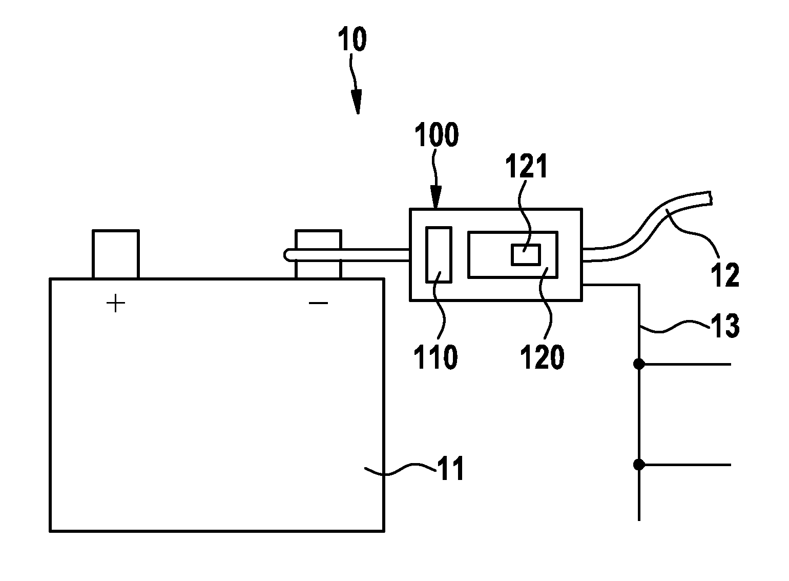
[0022]FIG. 1 shows a schematic illustration of a preferred embodiment 100 of a battery monitoring device in accordance with the invention in an energy supply system 10 of a motor vehicle. The battery monitoring device 100 is connected between a negative pole of a starter battery 11 and a battery cable 12 of the motor vehicle.
[0023]The battery monitoring device 100 comprises a measuring part 110 that measures a series of variables of the battery 11. In addition, the battery monitoring device 100 comprises a data processing unit 120 for evaluating the measured variables and for determining the battery state. The data processing unit 120 comprises a non-volatile memory 121 for storing inter alia a datum that characterizes a critical battery state. The battery monitoring device 100 is connected via a connection 13, in particular a bus connection, to further components of the vehicle, in particular control devices.
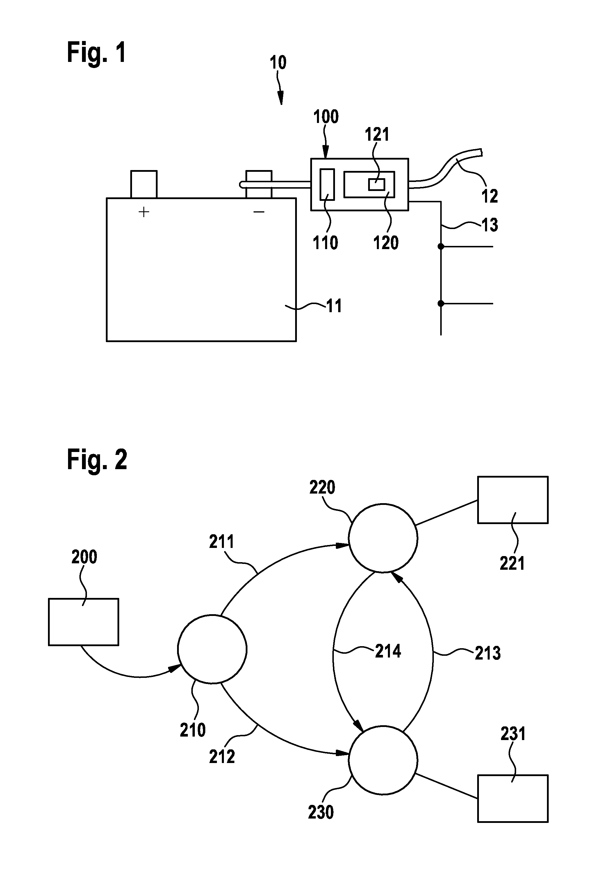
[0024]FIG. 2 illustrates a preferred embodiment of the invention in the fo...
PUM
 Abstract
Description
Claims
Application Information
 - R&D
- Intellectual Property
- Life Sciences
- Materials
- Tech Scout
- Unparalleled Data Quality
- Higher Quality Content
- 60% Fewer Hallucinations
Browse by: Latest US Patents, China's latest patents, Technical Efficacy Thesaurus, Application Domain, Technology Topic, Popular Technical Reports.
© 2025 PatSnap. All rights reserved.Legal|Privacy policy|Modern Slavery Act Transparency Statement|Sitemap|About US| Contact US: help@patsnap.com


