
Printing system with self-purge, sediment prevention and fumes removal arrangements

Active Publication Date: 2013-06-06
XJET
View PDF8 Cites 43 Cited by
  • Summary
  • Abstract
  • Description
  • Claims
  • Application Information

AI Technical Summary

Benefits of technology

The present invention is about a method for printing using an inkjet head. The method involves keeping the nozzles plate, which contains the nozzles, wet during printing to prevent the accumulation of solid sediment on the nozzles plate. The technical effect of this is that it improves the accuracy and reliability of printing.

Problems solved by technology

One of the disadvantages of conventional purging techniques is that a printing head needs to be shifted from the printing area to a maintenance area where the purged liquid is able to drip from the head, and any liquid that drips from the head will not adversely affect the printing process.
As the vacuum head does not contact the nozzle plate, there is suction from all sides of the vacuum head (not just from the direction of the nozzle plate) resulting in low cleaning efficiency of the nozzle plate.
Disadvantages to conventional vacuum wiping include cost, printing speed, reliability, and quality of wiping.
Examples of the disadvantages of conventional vacuum wiping include: (a) The printing head requires shifting from the printing area to a maintenance area due to the possibility of purged liquid dripping from the printing head.
(b) Shifting a printing head from a printing area to a maintenance area takes time, resulting in reduced printing speed and correspondingly increased cost.
Higher precision elements increase the cost of a printing machine, and the reliability of wiping is dependent on maintaining high precision.
The time required for effective wiping reduces printing speed and correspondingly increases printing cost.

Method used


Image

  • Printing system with self-purge, sediment prevention and fumes removal arrangements
  • Printing system with self-purge, sediment prevention and fumes removal arrangements
  • Printing system with self-purge, sediment prevention and fumes removal arrangements

Examples


Embodiment Construction

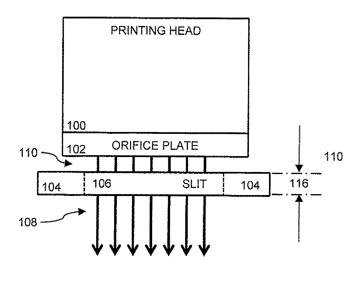
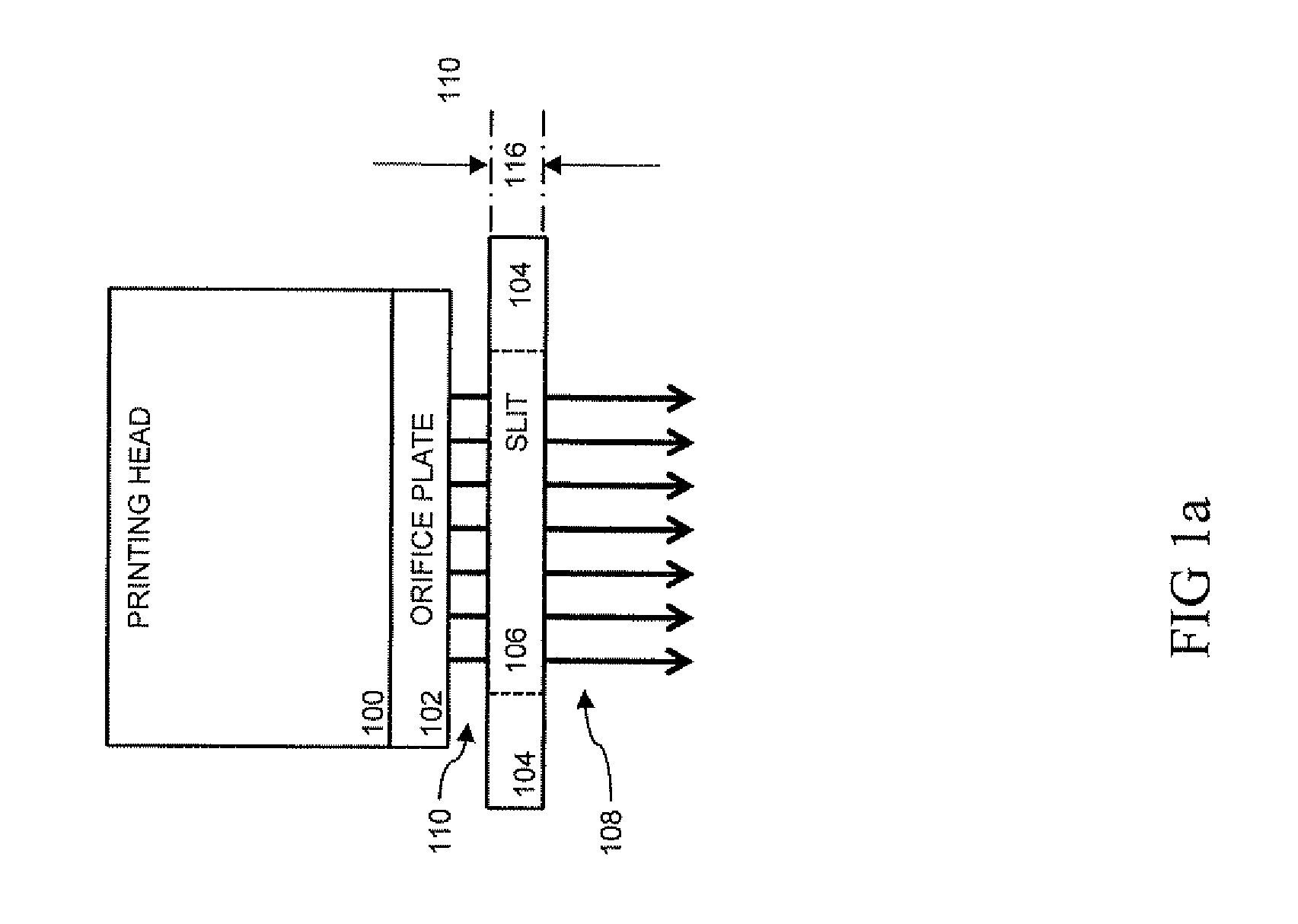
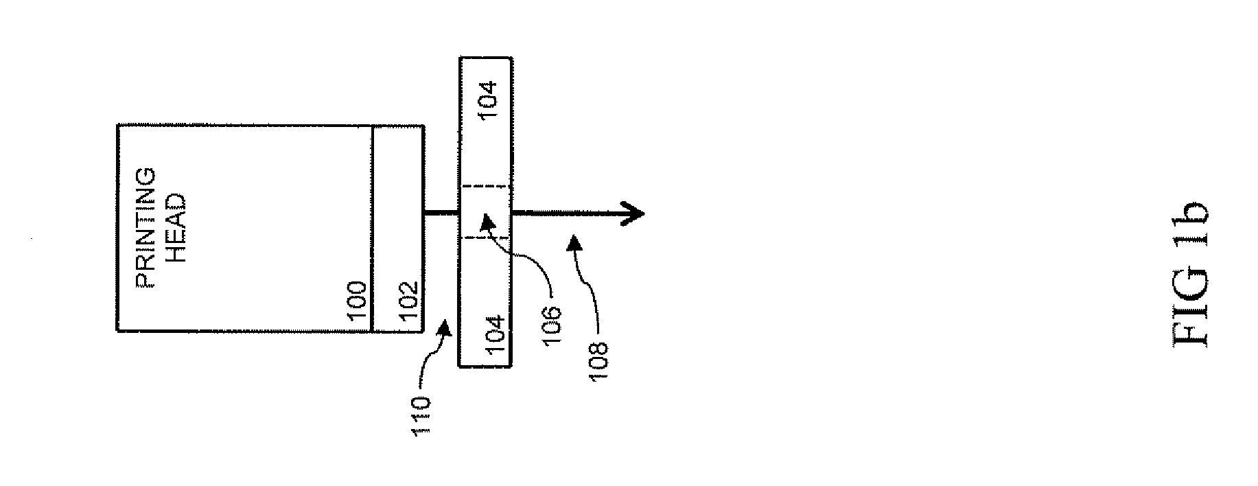
[0061]Embodiments of the present invention provide a printing system with an integrated self-purge, sediment prevention and fumes removal arrangements without purged liquid dripping from the nozzle plate. The integrated self-purge arrangement is desirable for high quality cleaning with lower costs and higher reliability than current techniques. In particular, the present embodiment facilitates printing while eliminating the time required for shifting the printing head to a maintenance area, as compared to the time required for conventional techniques. In addition, in a multi-head system (or a system with multiple groups of heads) where one maintenance area (or in general fewer maintenance areas than heads) are used for purging, the present embodiment facilitates reduced system complexity. For example, each head (or group of heads) has an integrated self-purge arrangement eliminating the need for competition and coordination of heads for maintenance areas. Although this embodiment is...


PUM

PropertyMeasurementUnit
Forceaaaaaaaaaa
Pressureaaaaaaaaaa
Areaaaaaaaaaaa

Abstract

A printing head assembly with integrated purge mechanism is disclosed. The printing head assembly comprises: (a) a liquid dispensing head comprising one or more dispensing nozzles enclosed in a nozzle plate, driven by at least first and second pressures, and (b) a shielding mask including an opening in front of the one or more nozzles, wherein the opening being configured such that when printing liquid is dispensed from the head driven by the first pressure, the liquid being dispensed in pulses through the opening in the shielding mask, and (ii) when purge printing liquid is dispensed from the head driven by the second pressure the liquid being drawn to a capillary gap formed between the shielding mask and the nozzle plate thereby removing the purge printing liquid from the nearby nozzles.

Description

FIELD OF THE INVENTION[0001]The present embodiment generally relates to the field of printing, and in particular, it concerns a printing system with an integrated self-purge, sediment prevention and fumes removal arrangements.BACKGROUND OF THE INVENTION[0002]It is known in the field of printing that inkjet printing heads require periodic purging to clean the printing nozzles, remove air bubbles, and maintain printing quality. Simply stated, inkjet printers operate by expelling a small volume of ink from a plurality of nozzles through corresponding small orifices in a nozzle plate held in proximity to a paper or front surface of a solar cell or other medium upon which printing or marks are to be placed. These orifices are arranged in a fashion in the nozzle plate such that the expulsion of droplets of ink from a selected number of nozzles relative to a particular position of the medium results in the production of a portion of a desired character or image. Controlled repositioning of...

Claims


Application Information

Patent Timeline
IPC IPC(8): B41J2/165
CPCB41J2/16523B41J2002/16558B41J2/16526B41J2/1714B41J2/16552B41J2002/16502B41J2/18B29C64/112B29C64/35B33Y10/00B33Y30/00B29C64/209B33Y40/00B29C64/357B41J2/16502B41J2/04566B41J2/165G01D15/18
Inventor KRICHTMAN, ELIMIMON, RONENGOTHAIT, HANAN
Owner XJET
Learn More