Wireless communication system, communication apparatus, communication method, and communication program
- Summary
- Abstract
- Description
- Claims
- Application Information
AI Technical Summary
Benefits of technology
Problems solved by technology
Method used
Image
Examples
first embodiment
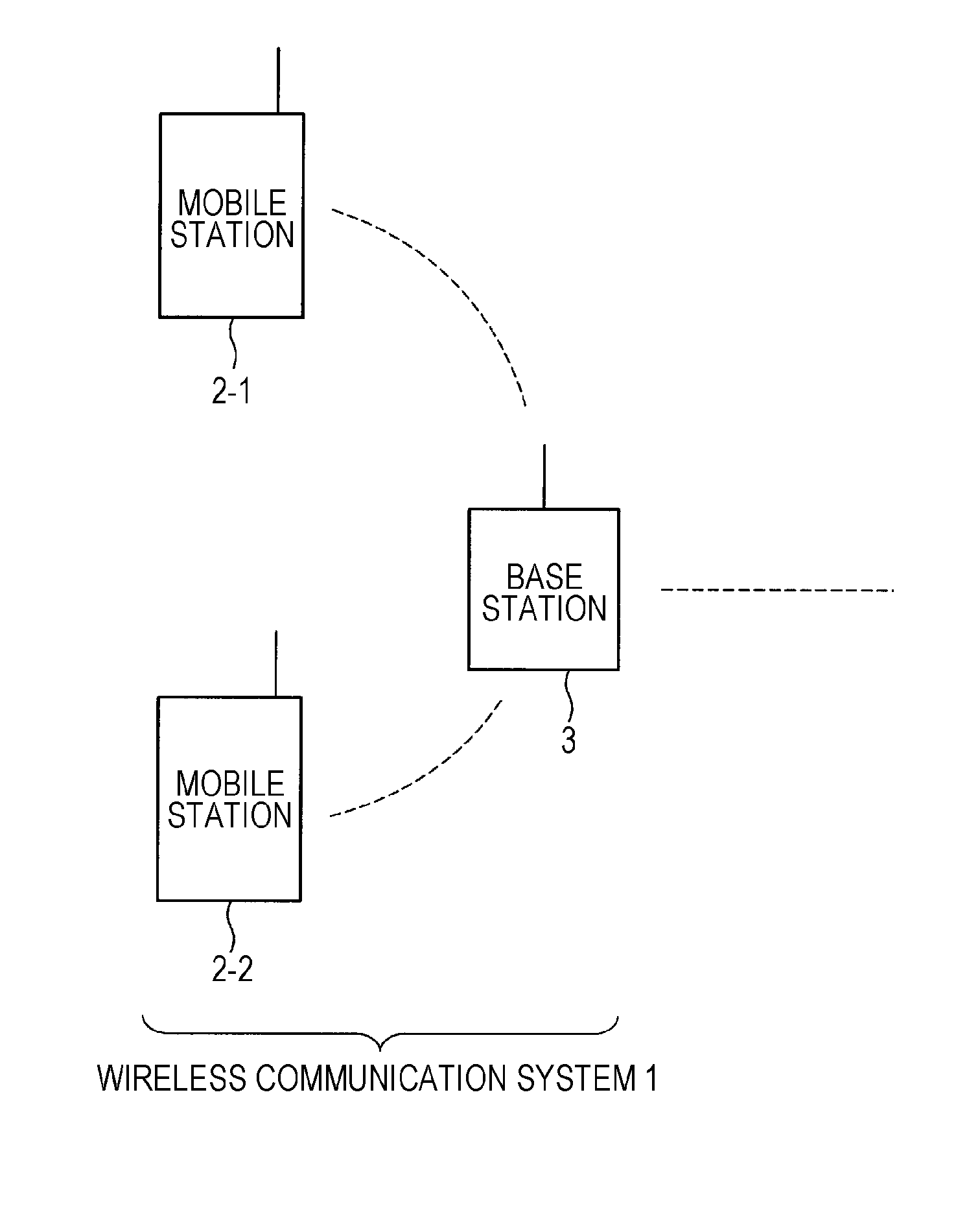
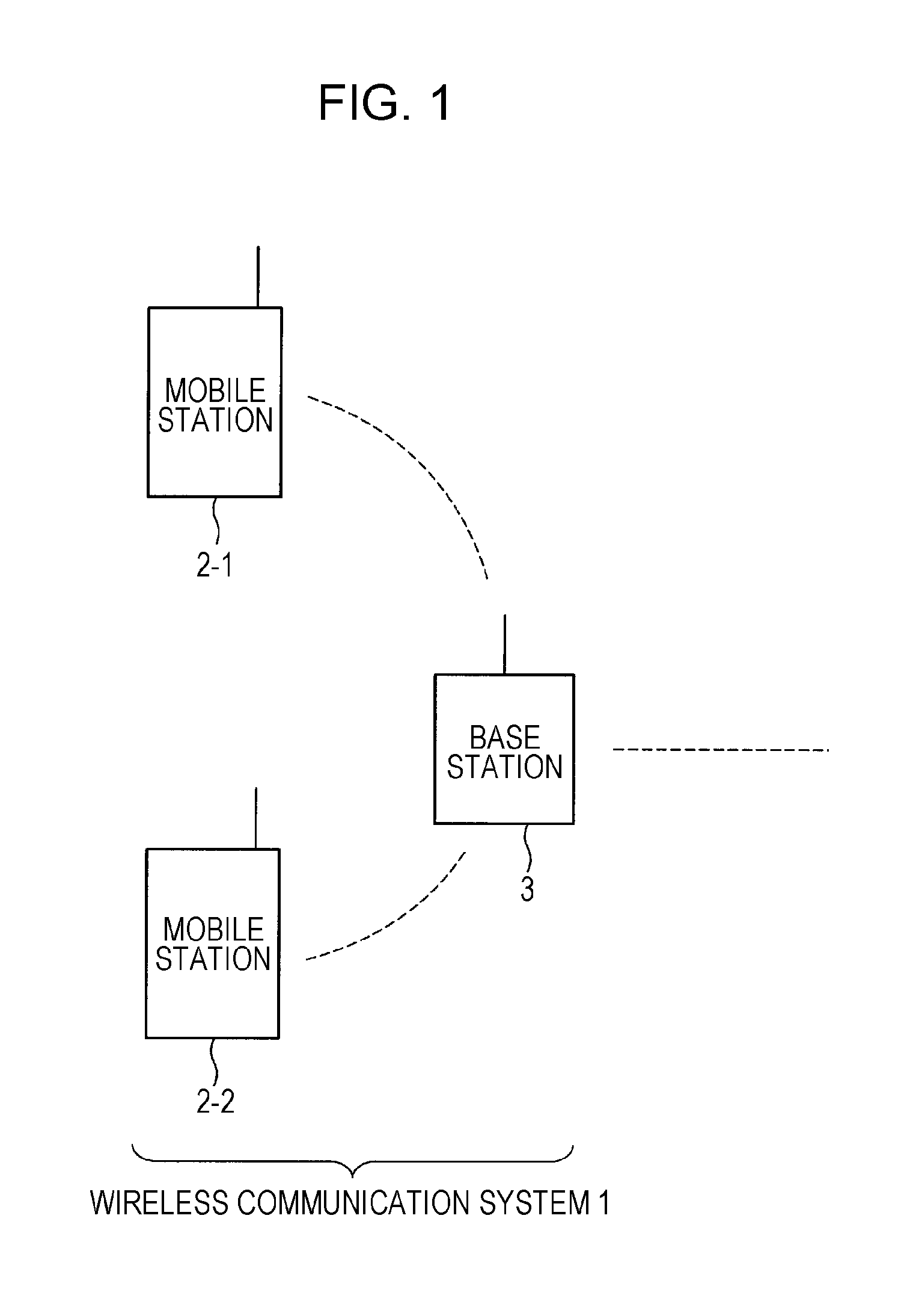
[0041]Hereinafter, embodiments of the present invention will be described in detail and with reference to the drawings. FIG. 1 illustrates an exemplary configuration of a wireless communication system 1. The wireless communication system 1 includes one or more mobile stations 2-1 and 2-2, and a base station 3. Although FIG. 1 depicts two mobile stations, these will be simply designated the mobile station 2 for convenience when it is not necessary to distinguish them. One mobile station 2-1 is a communication apparatus that transmits and receives information to and from the other mobile station 2-2 via the base station 3. A mobile station may be a mobile phone handset, for example. The base station 3 is a communication apparatus that receives information from the mobile stations 2-1 and 2-2, and transmits that information to the other mobile station 2-2 and 2-1, respectively. Electromagnetic waves propagating primarily through the air are used as the propagation channel for the trans...
second embodiment
[0105]Hereinafter, a second embodiment of the present invention will be described in detail and with reference to the drawings. This embodiment shares the configuration of the first embodiment unless specifically noted.
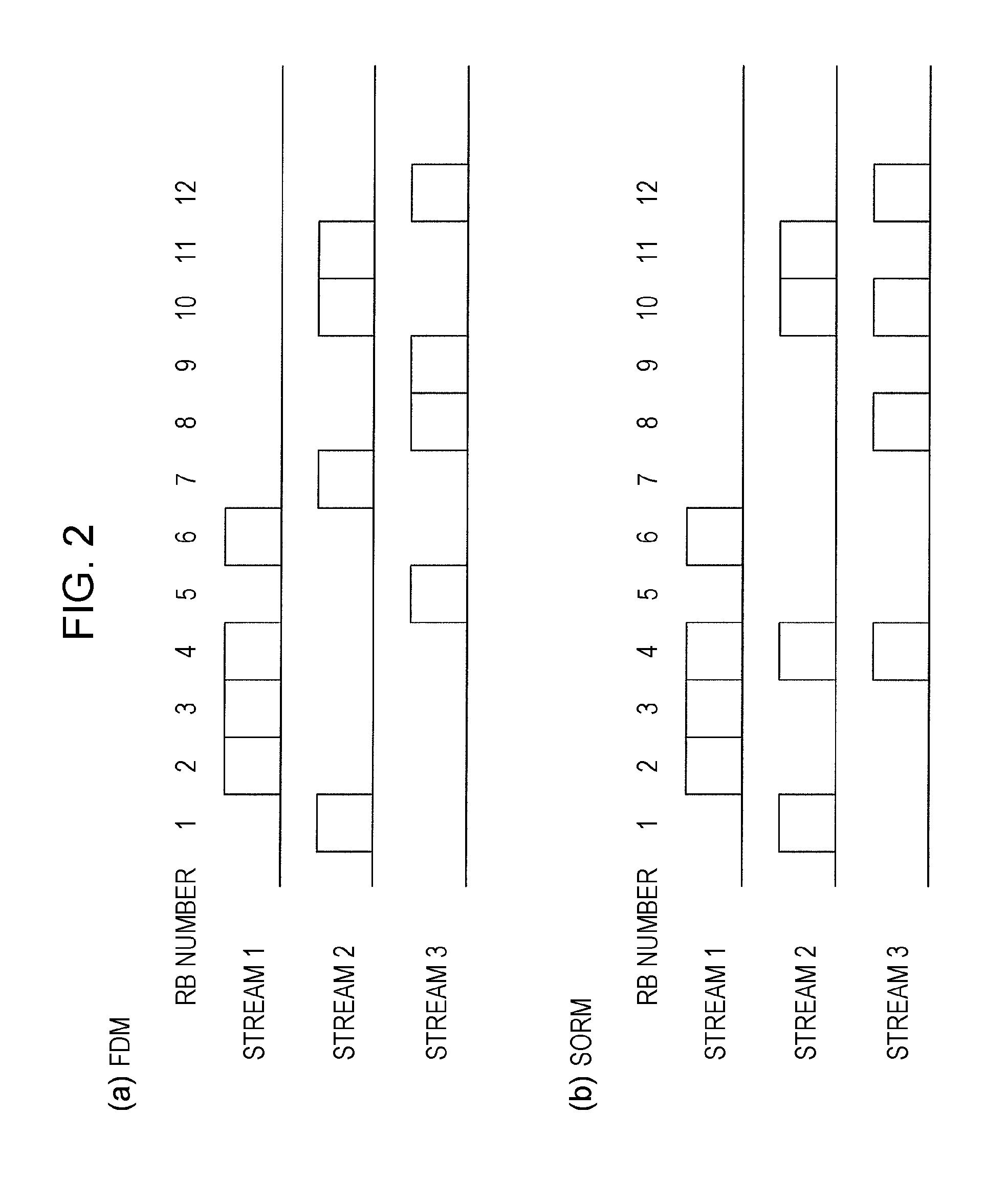
[0106]FIG. 9 is a configuration diagram illustrating an example of a base station 5 according to the present embodiment. The base station 5 includes a coding scheme determiner 321 in addition to the configuration of the base station 3 (FIG. 4). The RB allocation determiner 308 also outputs per-stream RB allocation information to the coding scheme determiner 321 as well as the transmitter 310. On the basis of the per-stream RB allocation information input from the RB allocation determiner 308, the coding scheme determiner 321 computes the overload ratio ol by counting the number of RBs overlapping between streams, and dividing that RB count by the number of RBs per stream.
[0107]The coding scheme determiner 321 also includes storage that stores overload ratios ol in ass...
third embodiment
[0117]Hereinafter, a third embodiment of the present invention will be described in detail and with reference to the drawings. This embodiment also shares the configuration of the first embodiment unless specifically noted. FIG. 11 is a configuration diagram illustrating an example of a base station 7 according to the present embodiment. The base station 7 includes a precoder determiner 331 in addition to the configuration of the base station 3. The RB allocation determiner 308 also outputs per-stream RB allocation information to the precoder determiner 331 as well as the transmitter 310. On the basis of the per-stream RB allocation information input from the RB allocation determiner 308, the precoder determiner 331 computes the overload ratio ol by counting the number of RBs overlapping between streams, and dividing that RB count by the number of RBs per stream.
[0118]The precoder determiner 331 includes storage that stores multiple combinations of precoder variable information for ...
PUM
 Abstract
Description
Claims
Application Information
 - R&D
- Intellectual Property
- Life Sciences
- Materials
- Tech Scout
- Unparalleled Data Quality
- Higher Quality Content
- 60% Fewer Hallucinations
Browse by: Latest US Patents, China's latest patents, Technical Efficacy Thesaurus, Application Domain, Technology Topic, Popular Technical Reports.
© 2025 PatSnap. All rights reserved.Legal|Privacy policy|Modern Slavery Act Transparency Statement|Sitemap|About US| Contact US: help@patsnap.com


