Rapid Energy Release Burners And Methods For Using The Same

a burner and energy release technology, applied in the field of oxyfuel burners, can solve the problems of high flue gas temperature, inefficient heat transfer to scraps, etc., and achieve the effect of enabling rapid release of combustion energy and enhancing mixing between fuel and oxidizer streams

Active Publication Date: 2013-06-06
AIR PROD & CHEM INC
View PDF2 Cites 11 Cited by
  • Summary
  • Abstract
  • Description
  • Claims
  • Application Information

AI Technical Summary

Benefits of technology

[0006]A rapid energy release burner described herein solves problems associated with conventional burners and methods by including a high shape factor nozzle surrounded by an annular nozzl

Problems solved by technology

When conventional oxy-fuel burner technologies are used, the flame can form a cavity through

Method used


Image

  • Rapid Energy Release Burners And Methods For Using The Same
  • Rapid Energy Release Burners And Methods For Using The Same
  • Rapid Energy Release Burners And Methods For Using The Same

Examples


Embodiment Construction

[0041]An oxy-fuel burner is described that can facilitate the rapid release of combustion energy into the furnace. This is achieved by special geometrical configurations of fuel and oxidizer nozzles, resulting in a relatively voluminous flame that is capable of heating up a furnace charge more uniformly.

[0042]As used herein, the terms “oxidizer” and “oxidant” are used interchangeably to mean a gas having at least about 20.9% vol. % O2, and may have at least about 23 vol. % O2, or at least about 30 vol. % O2, or at least about 60 vol. % O2, or at least about 85 vol. % O2 or about 100% O2. As used herein, “fuel gas” can include any gaseous fuel capable of combusting in an oxidizer or oxidant.

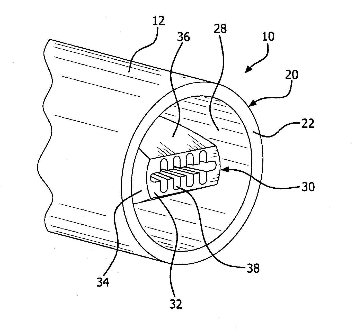
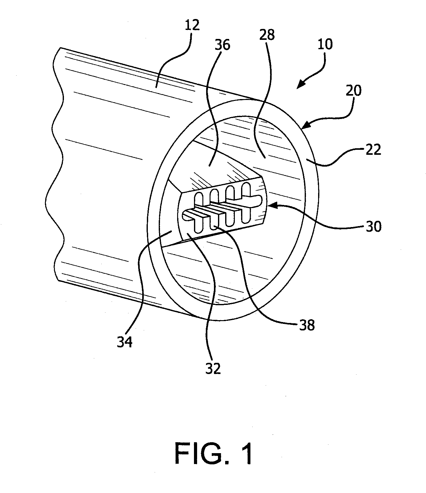
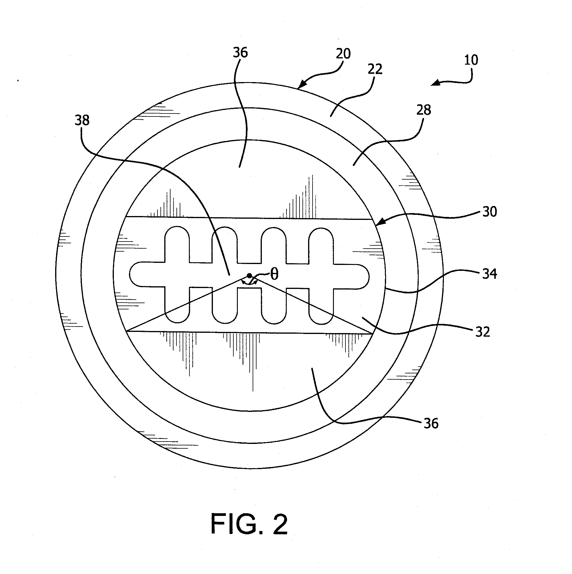
[0043]FIGS. 1-3B show an exemplary burner 10 having an outer conduit 12 and an inner conduit 14. The outer conduit 12 terminates in an annular nozzle 20 having a discharge end 22, and the inner conduit 14 terminates in a high shape factor (HSF) nozzle 30. The HSF nozzle 30 includes an outlet face ...


PUM


Abstract

A burner having a high shape factor nozzle including a nozzle opening having a shape factor from about 10 to about 75, the shape factor being defined as the square of the nozzle perimeter divided by twice the nozzle cross-sectional area, and an annular nozzle surrounding the high shape factor nozzle, wherein the high shape factor nozzle is configured to be supplied with one of a fuel gas and an oxidizer gas, and the annular nozzle is configured to be supplied with the other of a fuel gas and an oxidizer gas. A method of rapid energy release combustion, including supplying a fuel gas and an oxidizer gas to a burner having a high shape factor nozzle and an annular nozzle surrounding the high shape factor nozzle.

Description

CROSS-REFERENCE TO RELATED APPLICATIONS[0001]This application claims the priority of U.S. Provisional Patent Application No. 61,565,560 filed on Dec. 1, 2011, which is incorporated by reference herein in its entirety. This application is related to application Ser. No. ______ entitled “STAGED AIR-OXY-FUEL BURNERS AND METHODS FOR USING THE SAME”, Attorney Docket No. 07566ZP2 USA, filed contemporaneously with this Application on Nov. 30, 2012, assigned to the assignee of the present disclosure.BACKGROUND OF THE INVENTION[0002]The subject matter of this invention relates to an oxy-fuel burner than enables rapid release of combustion energy.[0003]Oxy-fuel burners are used in a wide range of applications. In one application, oxy-fuel burners are employed for melting scrap within a furnace (e.g., in connection with aluminum recycling). In some applications, the charging practice for introducing scrap into the furnace causes the metal to be located relatively close to the face of the burne...

Claims


Application Information

Patent Timeline
IPC IPC(8): F23D14/58
CPCF23D14/58Y02E20/344F23D14/32F23D14/22Y02E20/34F23D14/583
Inventor GANGOLI, SHAILESH PRADEEPSLAVEJKOV, ALEKSANDAR GEORGICOLE, JEFFREY D.
Owner AIR PROD & CHEM INC
Why Eureka
Try Eureka