Connecting unit, band and electronic device including band

a technology of connecting unit and electronic device, which is applied in the direction of bracelets, mechanical devices, couplings, etc., can solve the problems of inability to maintain strength, easy deformation, and easy damage to the fastening ring, and achieve the effect of easy adjustment and easy attachment or removal

Active Publication Date: 2013-06-13
CASIO COMPUTER CO LTD
View PDF0 Cites 21 Cited by
  • Summary
  • Abstract
  • Description
  • Claims
  • Application Information

AI Technical Summary

Benefits of technology

[0012]An object of the present invention is to provide a connecting unit by which a segment member can be easily attached or removed without a special tool or technique, a band of which length can be adjusted easily by the connecting unit and an electronic device which includes the band.

Problems solved by technology

Therefore, as described in Patent Document 1, when a fastening ring for preventing falling off of the pin member is disposed inside the second pipe, the fastening ring is easily affected by the move between the segment members and is easily deformed due to applied pressure and ablation with use.
Further, there is also a possibility that strength cannot be maintained due to corrosion of the fastening ring and such like by sweat and such like coming in from between the first pipes and the second pipe.
In such case where a fastening ring is deformed or strength of the fastening ring is lowered, there is a problem that a pin member which is fastened to be fixed by the fastening ring is easy to fall off.
On the other hand, if the pin member is completely fixed so as not to fall off from the band, there is a problem that the segment member cannot be attached and removed without using a special tool or the like and a general user who purchased a wristwatch or the like including the band cannot adjust the length of the band easily.
Though a shop assistant or the like performs adjustment when the wristwatch or the like is purchased at a shop, it is inconvenient if the general user cannot attach and remove a segment member to adjust the size of the band by himself or herself when size adjustment is needed after purchase of the wristwatch or when the wristwatch is purchased by mail order, for example.

Method used


Image

  • Connecting unit, band and electronic device including band
  • Connecting unit, band and electronic device including band
  • Connecting unit, band and electronic device including band

Examples


Embodiment Construction

[0036]Hereinafter, a preferred embodiment of a connecting unit, a band and an electronic device including the band according to the present invention will be described with reference to FIGS. 1 to 11.

[0037]Though a case where an electronic device according to the present invention is a wristwatch will be described hereinafter, an embodiment to which the present invention can be applied is not limited to this.

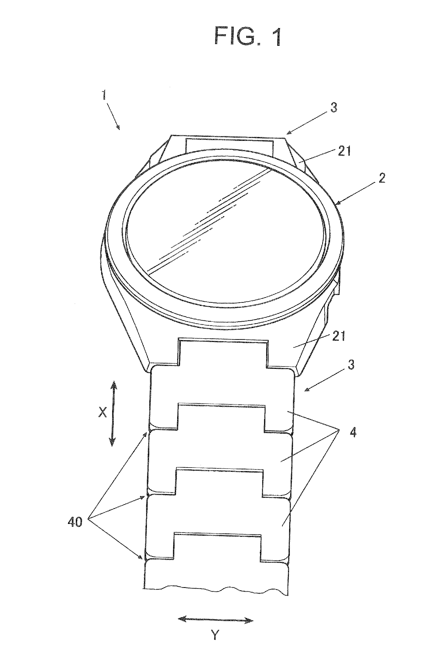
[0038]FIG. 1 is a schematic view of a wristwatch as an electronic device according to the embodiment.

[0039]As shown in FIG. 1, in the embodiment, a wristwatch 1 includes a band 3 and a case 2 as an outer case to which the band 3 is attached.

[0040]At both of the upper and lower end portions (the upper and lower end portions in FIG. 1) of the case 2, that is, at the end portion of 12 o'clock side and at the end portion of 6 o'clock side, band attaching sections 21 to which the band 3 is attached are formed.

[0041]Inside the case 2, a display unit and such like of the wristwatch 1 a...


PUM


Abstract

A connecting unit including an outer frame member having a pair of hole sections, a pair of first connecting sections and long holes for inserting a controller. The connecting unit further includes a holding frame body which includes through-holes at positions corresponding to the long holes, slide members which include a second connecting section which protrudes and retracts from the pair of hole sections and slide in the extending direction of the long holes by slide operation of the controller, elastic members which bias the slide members to an opposite direction of an insertion direction of the controller and a locking member which locks the slide member at a position where connection between the second connecting section and the first connecting section of the adjacent segment members is released.

Description

BACKGROUND OF THE INVENTION[0001]1. Field of the Invention[0002]The present invention relates to a connecting unit, a band and an electronic device including the band.[0003]2. Description of Related Art[0004]Generally, as a band such as a wristwatch band formed by connecting a plurality of segment members and as a connecting unit of the segment members, in cited document 1 (Japanese Utility Model Application Laid Open Publication No. S60-182811), there is described a type which is configured so that a pair of first pipes are provided at an end of the segment member, a second pipe disposed between the pair of first pipes is provided at an end of another segment member which is connected to the segment member, and a pin member is inserted to each pipe of the first and the second pipes in the state where the second pipe and the pair of first pipes are disposed in series to sequentially connect a plurality of segment members.[0005]Such a band and a connecting unit thereof of a wristwatc...

Claims


Application Information

Patent Timeline
Patent Type & Authority Applications(United States)
IPC IPC(8): A44C5/00F16C11/12
CPCA44C5/0053Y10T403/32606A44C5/02F16C11/12
Inventor ASAMI, KIYOSHI
Owner CASIO COMPUTER CO LTD
Why Eureka
Try Eureka