Water and oil separation system

Active Publication Date: 2013-06-13
BOARD OF TRUSTEES OPERATING MICHIGAN STATE UNIV
View PDF1 Cites 36 Cited by
  • Summary
  • Abstract
  • Description
  • Claims
  • Application Information

AI Technical Summary

Benefits of technology

[0006]The present separation system is advantageous over conventional devices in that the present system is expected to more efficiently and completely perform separation, reduce fouling, and be more cost effective in use. The present system advantageously benefits from a synergistic combination of a hydrocyclone with mu

Problems solved by technology

Various devices have been tried

Method used


Image

  • Water and oil separation system
  • Water and oil separation system
  • Water and oil separation system

Examples


Embodiment Construction

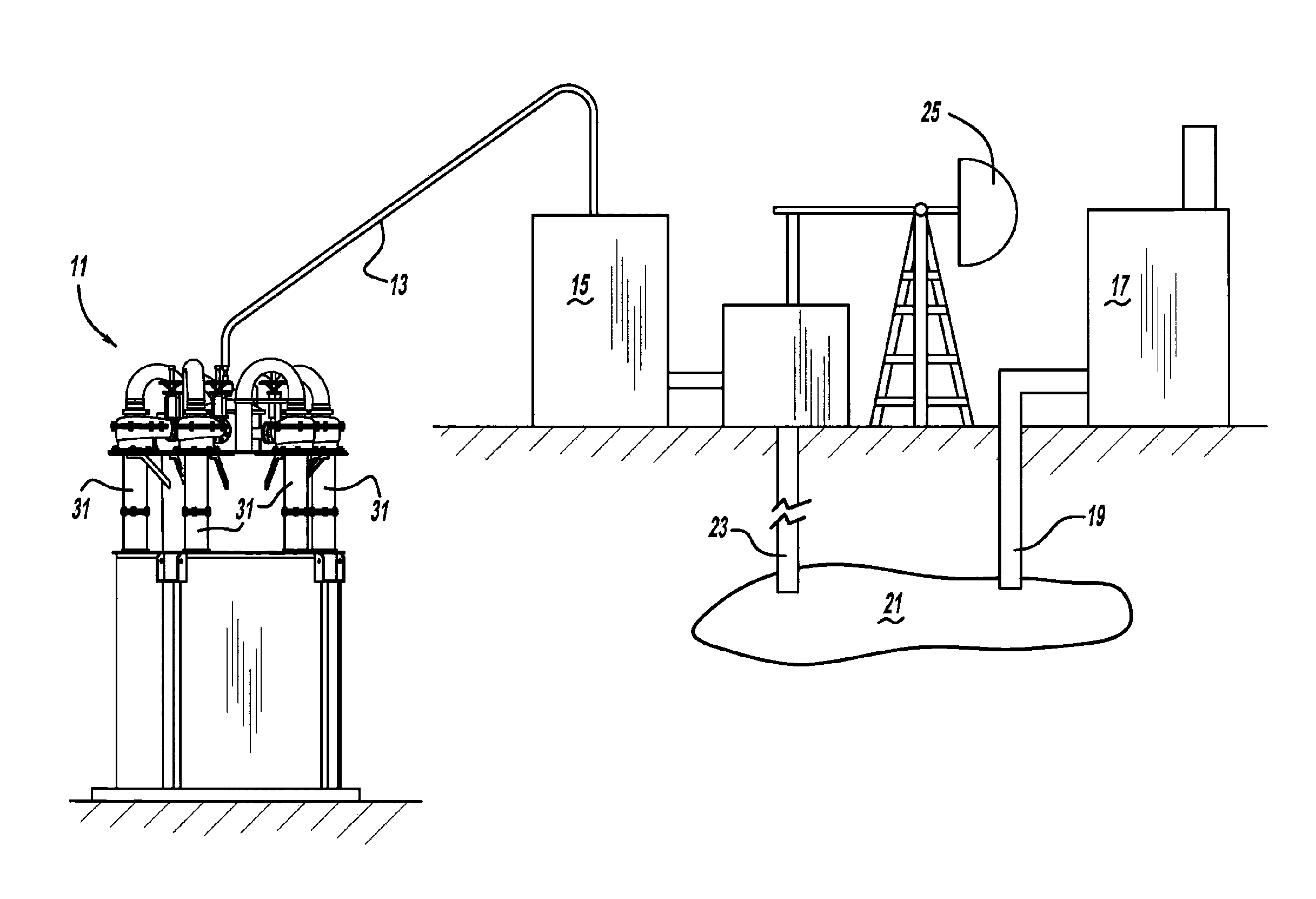
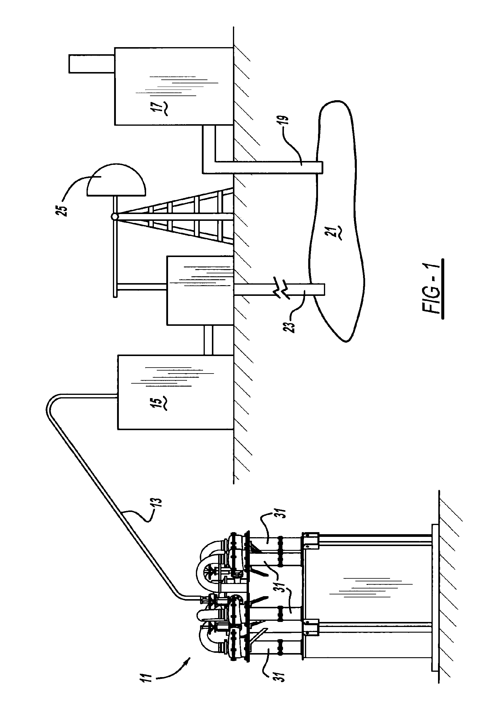
[0014]A water and oil separation and purification system 11 preferably includes two tubular, concentrical membranes with opposite affinities to water (one hydrophilic and another hydrophobic or superhydrophobic) and a hydrocyclonic flow between the membranes. In the application shown in FIG. 1, separation system 11 is fed an oil and water mixture by way of a feed pipe 13 connected to a storage tank 15. A boiler 17 creates steam which is injected underground through an insulated tube 19 to loosen up tar sands or other heavy hydrocarbon or oil deposits 21. The steam / water and oil mixture are then pumped up the same or a different tube 23 by an oil well pump 25 and transported to storage tank 15. In another application, separation system 11 is mounted to a watercraft (not shown) such as a boat equipped with oil skimmers, off-shore oil platform, or other flotation device, which includes an inlet for receiving an oil-and-water mixture resulted from an oil spill into sea water or generate...


PUM

PropertyMeasurementUnit
Lengthaaaaaaaaaa
Pore sizeaaaaaaaaaa
Flow rateaaaaaaaaaa

Abstract

A separation system includes at least a hydrocyclone and one or more membranes. In another aspect, a separation system includes a membrane having graduated and/or asymmetrical pore sizes. A further aspect of a separation system includes an inner membrane, an outer membrane and a hydrocyclonic flow between the membranes.

Description

CROSS-REFERENCE TO RELATED APPLICATION[0001]This application claims the benefit of U.S. Provisional Application Ser. No. 61 / 373,991, filed on Aug. 16, 2010, which is incorporated by reference herein.STATEMENT OF GOVERNMENT RIGHTS[0002]A portion of this invention was made with U.S. government support under grant OISE-0530174 from the National Science Foundation. The U.S. government may have certain rights in this invention.BACKGROUND AND SUMMARY[0003]The present disclosure relates generally to liquid-liquid separation and more particularly to an oil and water separation system using a membrane.[0004]Separation of oil from water has been a longstanding concern. Various devices have been tried but often with mediocre results. Hydrocyclones are generally known but none which circulate the oil / water mixture between membranes or which utilize various advantageous membrane characteristics. Exemplary conventional devices are disclosed in the following: U.S. Pat. No. 7,569,671 entitled “Meth...

Claims


Application Information

Patent Timeline
IPC IPC(8): C02F1/40E21B43/34
CPCB01D17/0217C02F1/40B01D63/06B01D63/08B01D63/16B01D65/08B01D69/02B01D69/12B01D71/024B01D71/34B01D71/36B01D2321/2033B01D2325/36B01D2325/38C02F1/38C02F1/444C02F2101/32E21B43/34B01D17/085
Inventor TARABARA, VOLODYMYRSHAN, WENQIAN
Owner BOARD OF TRUSTEES OPERATING MICHIGAN STATE UNIV
Why Eureka
Try Eureka