Magnetic levitation type vacuum pump and magnetic levitation device

a vacuum pump and magnetic levitation technology, which is applied in the direction of machines/engines, mechanical equipment, liquid fuel engines, etc., can solve the problems of affecting the control of magnetic levitation, reducing the current component corresponding to the carrier wave signal, and affecting the position measurement of the supported body which uses the carrier wave. the effect of increasing the current componen

Active Publication Date: 2013-06-13
SHIMADZU CORP
View PDF0 Cites 11 Cited by
  • Summary
  • Abstract
  • Description
  • Claims
  • Application Information

AI Technical Summary

Benefits of technology

[0014]According to the exemplary embodiments of the present invention, the carrier wave current component can be increased while suppressing the effect on the magnetic levitation control.

Problems solved by technology

When the coil turns are reduced in order to improve the coil characteristics (e.g., loss due to inductance, distributed capacitance regarding to inductance) regarding (e.g., loss due to inductance, distributed capacitance regarding to inductance) regarding to the carrier wave as well as in order to increase the carrier wave current, it may lead to a problem that the magnetic levitation control is affected since the desired magnetic levitation force cannot be obtained, etc.
However, if the coil turns of the electromagnet is increased, the carrier wave current component (the current component corresponding to the carrier wave signal) is decreased and the position measurement of the supported body which uses the carrier wave becomes harder.
In addition, the deterioration of the coil characteristics at high frequencies cannot be neglected.

Method used


Image

  • Magnetic levitation type vacuum pump and magnetic levitation device
  • Magnetic levitation type vacuum pump and magnetic levitation device
  • Magnetic levitation type vacuum pump and magnetic levitation device

Examples


Embodiment Construction

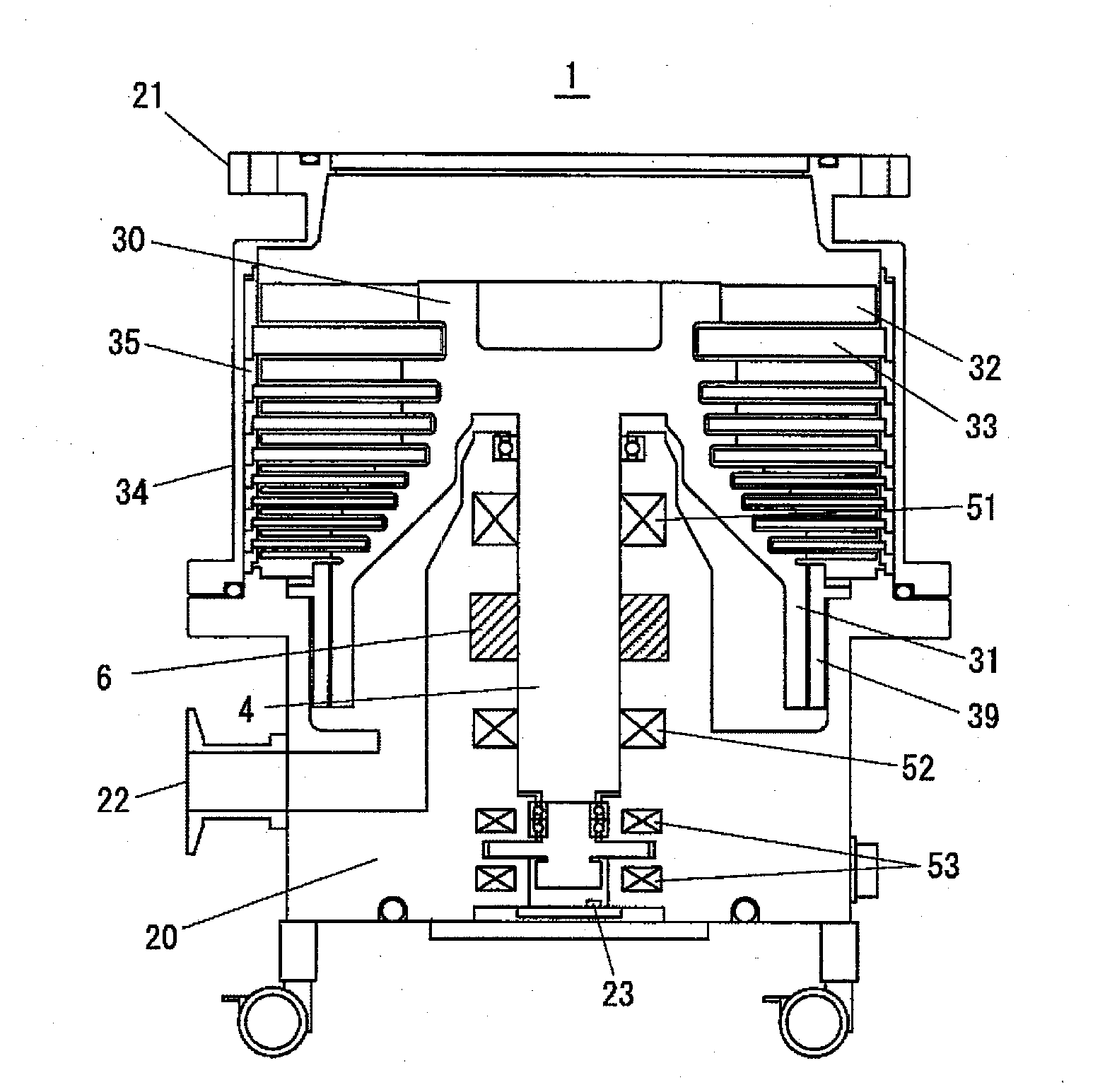
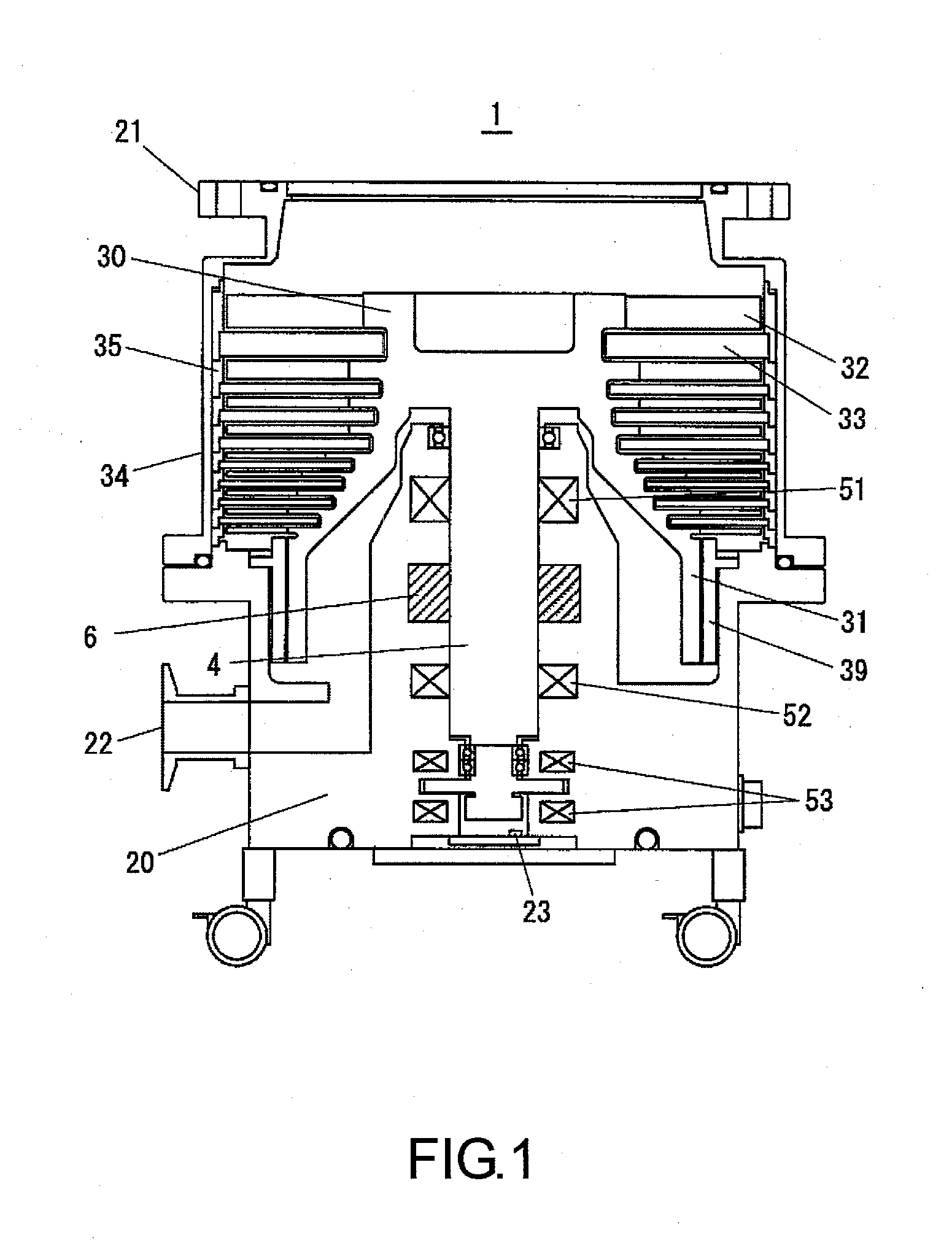
[0027]An exemplary embodiment according to the present invention is described in the following with reference to the accompanying drawings. FIG. 1 is a schematic cross-sectional view of the magnetic levitation type turbo molecular pump adapted to a sensorless magnetic levitation device according to an exemplary embodiment of the present invention. As shown in FIG. 1, the turbo molecular pump includes a pump unit 1 and a control unit (not shown) for driving the pump unit 1. The control unit connected to the pump unit 1 includes a magnetic bearing control section and a motor driving control section for rotationally driving the motor 6.

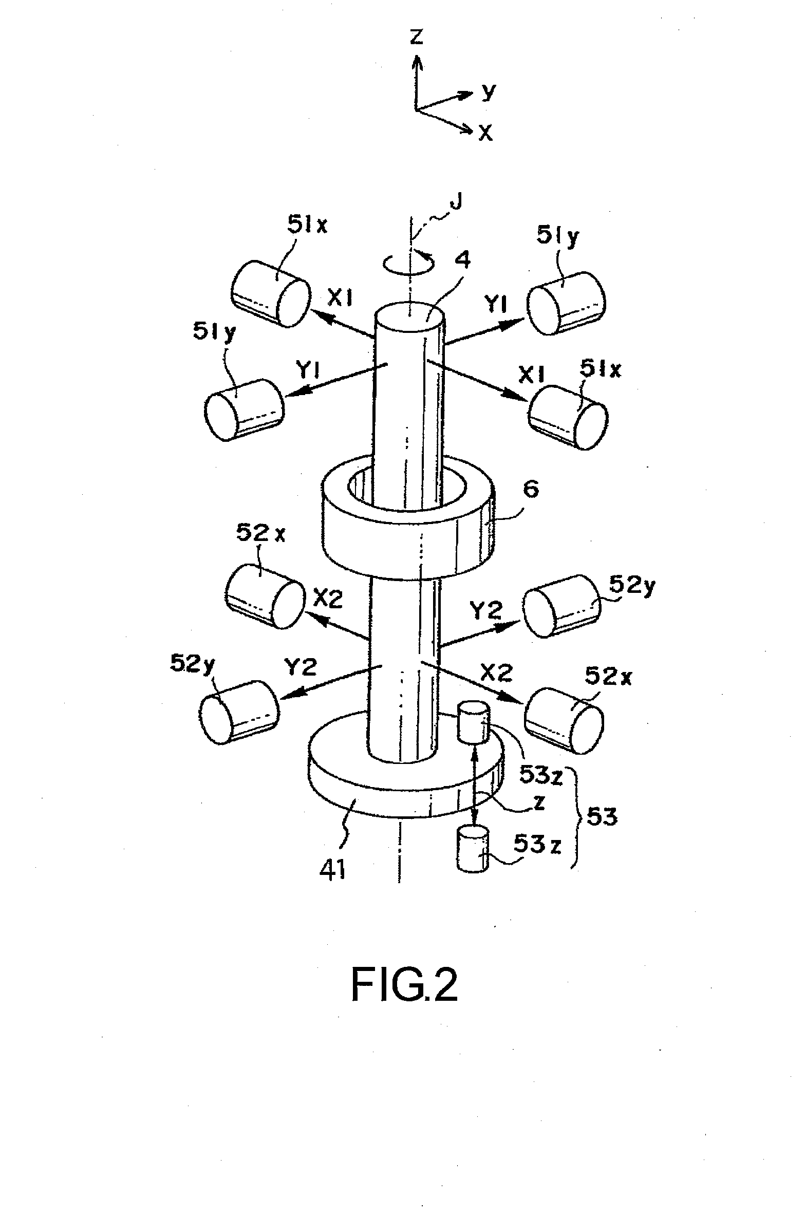
[0028]The rotor 30 is supported in a non-contact manner by a 5-axis control type magnetic bearing that includes radial magnetic bearings 51, 52 and axial magnetic bearings 53. The magnetically levitated rotor 30 which is rotatable by a magnetic bearing is rotationally driven in high speed by the motor 6. For example, a DC brushless motor is used as the m...


PUM


Abstract

A magnetic levitation type vacuum pump includes an electromagnet magnetically levitating a rotor by a magnetic force, an electromagnet driving circuit supplying an electromagnet current including a magnetic levitation control current component and a carrier wave current component having a frequency band higher than the magnetic levitation control current component to the electromagnet coil, a levitated position detecting circuit detecting the carrier wave current component and generating a levitated position signal of the rotor, a magnetic levitation control circuit inputting a current command of the magnetic levitation control current component to the electromagnet driving circuit based on the levitated position signal. The electromagnet coil has a primary coil and a secondary coil connected in parallel with the primary coil. An interrupting circuit connected in series with the secondary coil for the carrier wave current component passing therethrough and interrupting the magnetic levitation control current component is further included.

Description

CROSS-REFERENCE TO RELATED APPLICATION[0001]This application claims the priority benefit of Japan application serial no. 2011-268973, filed on Dec. 8, 2011 and Japan application serial no. 2012-207762, filed on Sep. 21, 2012. The entirety of each of the above-mentioned patent applications is hereby incorporated by reference herein and made a part of this specification.BACKGROUND OF THE INVENTION[0002]1. Field of the Invention[0003]The present invention relates to a magnetic levitation type vacuum pump and a magnetic levitation device.[0004]2. Description of Related Art[0005]In a turbo molecular pump in which the rotor is magnetically levitated by using a superimposed sensorless magnetic levitation device, a carrier wave of higher frequency whose frequency band is subject to a magnetically levitation control is superimposed to a driving current of the electromagnet for magnetic levitation so that the distance between the electromagnet and the rotor is measured from the voltage value,...

Claims


Application Information

Patent Timeline
Patent Type & Authority Applications(United States)
IPC IPC(8): H02K7/09
CPCH02K7/09F04D29/058F16C32/0444F04D19/04F16C2360/45
Inventor KOZAKI, JUNICHIRONAGANO, YOSHIHIROOFUJI, MASAKI
Owner SHIMADZU CORP
Why Eureka
Try Eureka