LED driver apparatus

Active Publication Date: 2013-06-13
MAGNACHIP SEMICONDUCTOR LTD
View PDF10 Cites 4 Cited by
  • Summary
  • Abstract
  • Description
  • Claims
  • Application Information

AI Technical Summary

Benefits of technology

The LED driver apparatus described in this patent synchronizes its own internal oscillator to match the needs of the LED array, resulting in a constant output current and voltage, and less ripple.

Problems solved by technology

However, because the LCDs are non-emitting device and cannot inherently emit light, separate backlights are necessary to supply light to LC panels.
However, the CCLFs are undesirable because they may cause environment pollutions due to mercury, have a low response time and lower reproducibility, and are not appropriate for lightness, thinness, shortness, and smallness of the LC panel.
Therefore, because the frequency of the oscillator is affected by a dimming frequency at a point of synchronization time, noise occurs when the dimming frequency is in an audible frequency band.

Method used


Image

  • LED driver apparatus
  • LED driver apparatus
  • LED driver apparatus

Examples


Embodiment Construction

[0041]Hereinafter, exemplary configuration will be described in greater detail with reference to the accompanying drawings.

[0042]The following detailed description is provided to assist the reader in gaining a comprehensive understanding of the methods, apparatuses, and / or systems described herein. Accordingly, various changes, modifications, and equivalents of the methods, apparatuses, and / or systems described herein will be suggested to those of ordinary skill in the art. Also, descriptions of well-known functions and constructions may be omitted for increased clarity and conciseness. Throughout the drawings and the detailed description, unless otherwise described, the same drawing reference numerals will be understood to refer to the same elements, features, and structures. The relative size and depiction of these elements may be exaggerated for clarity, illustration, and convenience.

[0043]It will be understood that when an element is referred to as being “on,”“connected to,” or ...


PUM


Abstract

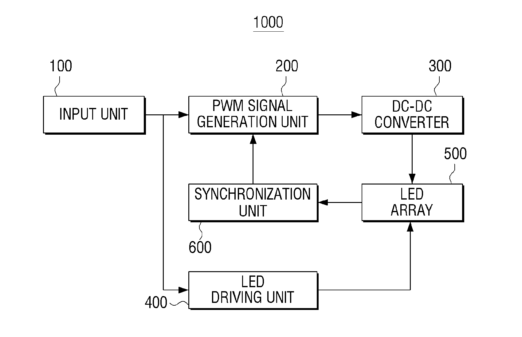
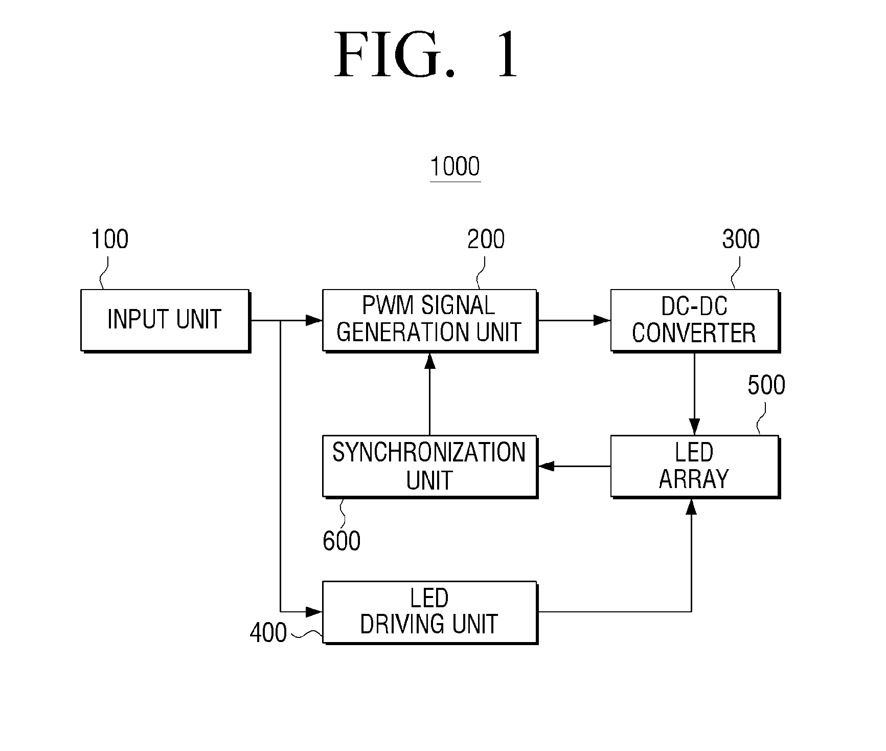
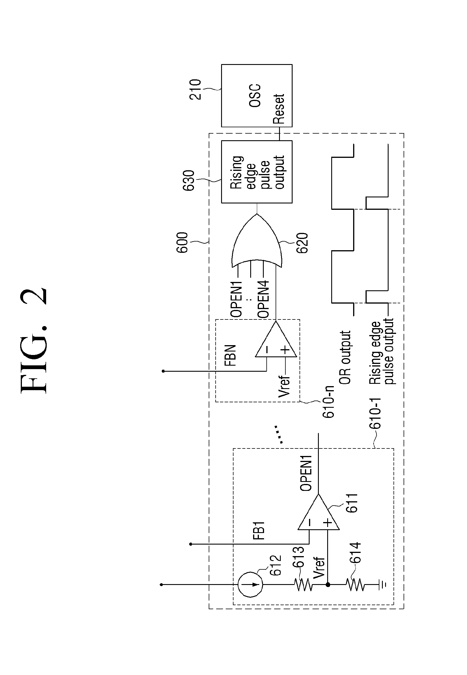
A light emitting diode (LED) driver apparatus is provided. The LED driver apparatus includes an input unit, a PWM signal generation unit, a DC-DC converter, an LED driving unit, and a synchronization unit. The input unit is configured to receive a dimming signal. The PWM signal generation unit is configured to generate a PWM signal using an oscillator having a preset frequency. The DC-DC converter is configured to provide a driving voltage to an LED array using the generated PWM signal. The LED driving unit is configured to drive the LED array using the received dimming signal. The synchronization unit is configured to reset the oscillator based on a driving state of the LED array.

Description

CROSS-REFERENCE TO RELATED APPLICATION[0001]This application claims priority from Korean Patent Application No. 10-2011-0130482, filed on Dec. 7, 2011, in the Korean Intellectual Property Office, the disclosure of which is incorporated herein by reference in its entirety.BACKGROUND[0002]1. Field[0003]The following description relates to a light emitting diode (LED) driver apparatus, and more particularly, to an LED driver apparatus configured to synchronize an oscillator therein according to a driving state of an LED array.[0004]2. Description of the Related Art[0005]Liquid crystal displays (LCDs) are thin and heavy and have a lower driving voltage and low power consumption compared to other display devices and are widely used. However, because the LCDs are non-emitting device and cannot inherently emit light, separate backlights are necessary to supply light to LC panels.[0006]Examples of backlights as light sources for the LCD include cold cathode fluorescent lamps (CCFLs), light ...

Claims


Application Information

Patent Timeline
IPC IPC(8): H05B37/02H05B44/00
CPCH05B37/02H05B33/0848H05B33/0815H05B45/14H05B45/37H05B45/325Y02B20/40G09G3/3406
Inventor LEE, WAN-JIKCHOI, JI-WONLIM, CHANG-SIK
Owner MAGNACHIP SEMICONDUCTOR LTD
Why Eureka
Try Eureka