
Methods and Systems to Convert a Pulse Power Demand to a Constant Power Draw

a technology of pulse power demand and constant power draw, applied in the direction of electric variable regulation, process and machine control, instruments, etc., can solve the problems of mechanical stress on the generator, affecting the power quality of other loads,

Active Publication Date: 2013-06-13
THE JOHN HOPKINS UNIV SCHOOL OF MEDICINE
View PDF2 Cites 10 Cited by
  • Summary
  • Abstract
  • Description
  • Claims
  • Application Information

AI Technical Summary

Benefits of technology

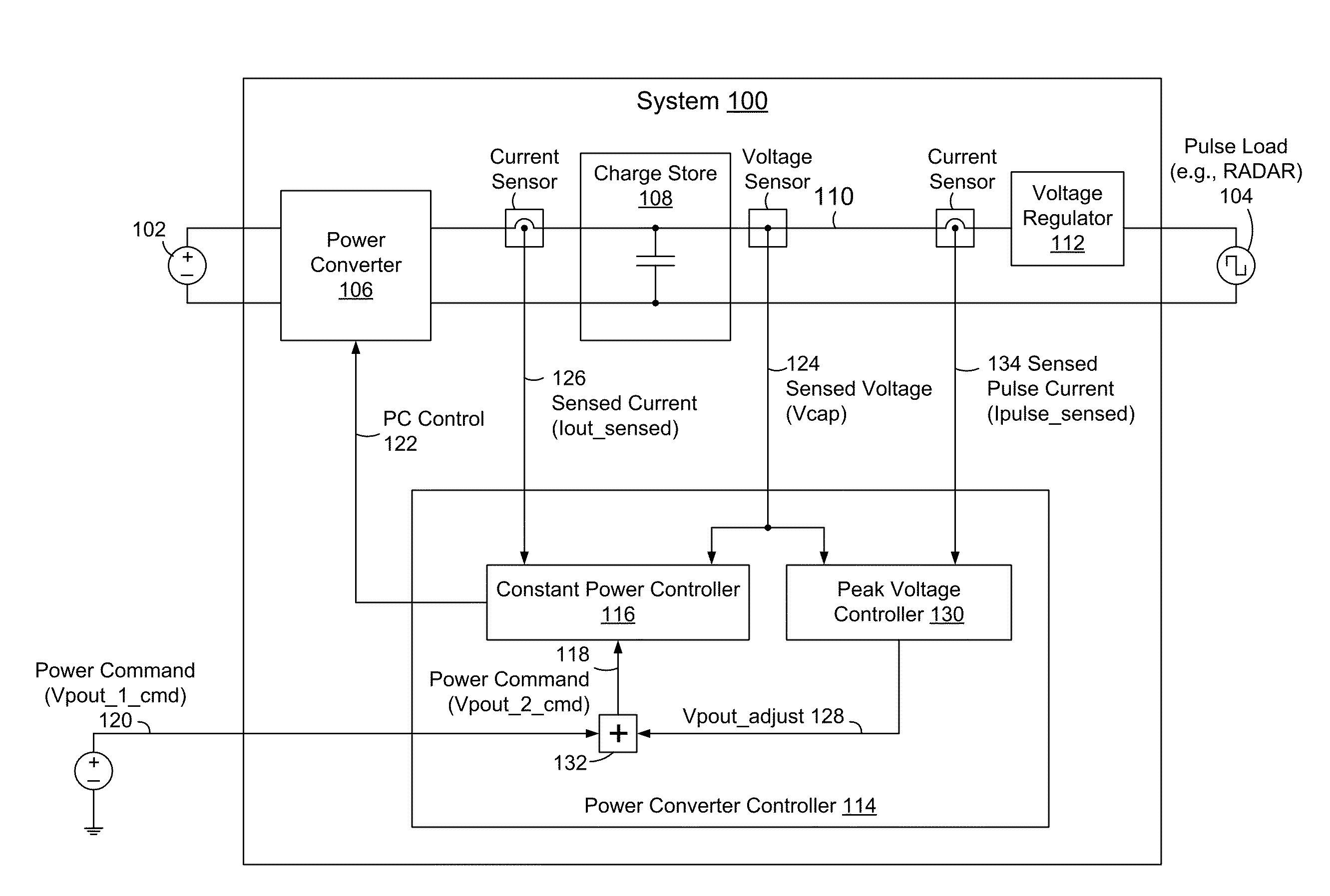
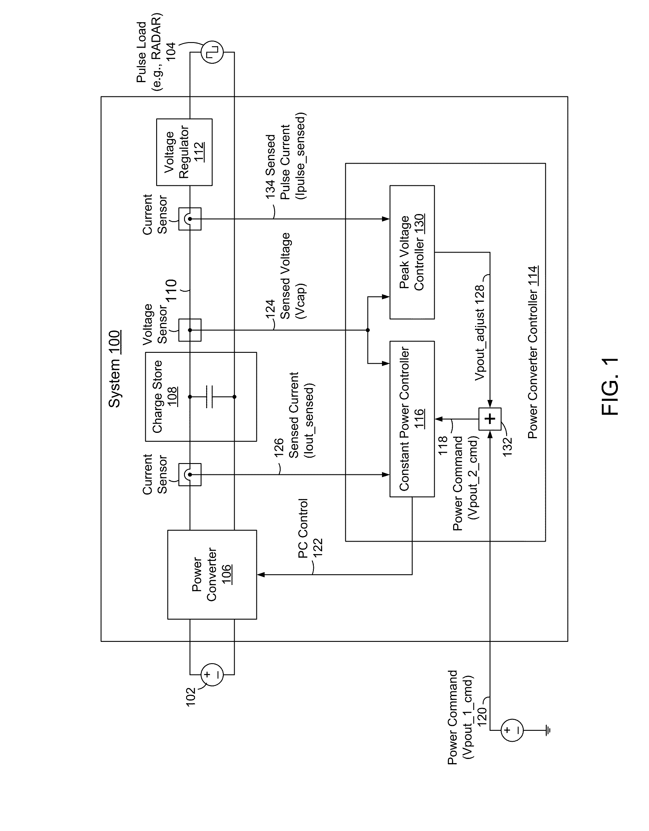
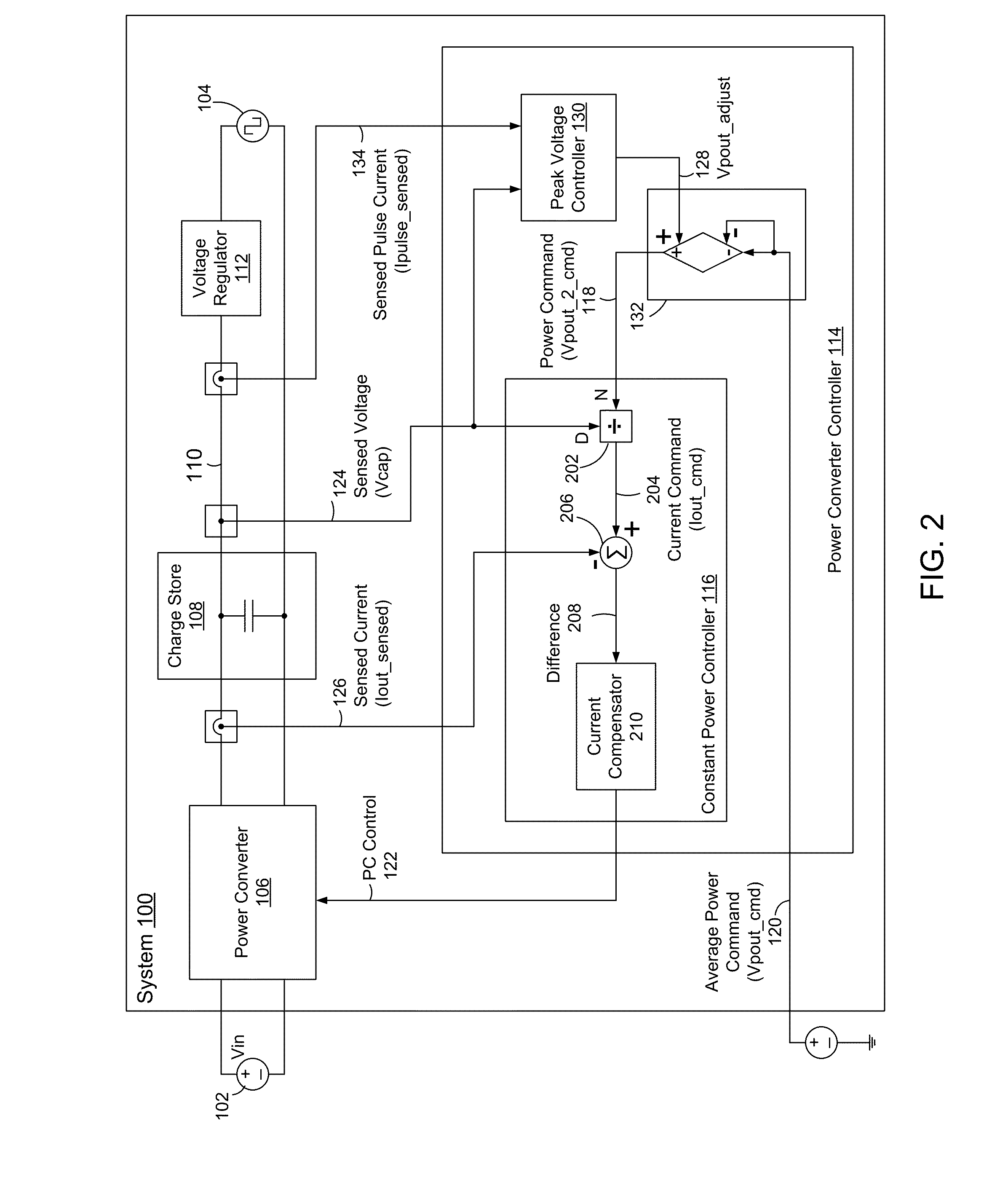
The patent describes methods and systems for controlling the power demand of a pulse load, such as a radar system, to a constant power source. It also includes compensating for time-varying effects that may alter the peak output voltage over time, such as temperature changes and component aging. A system includes a charge store, a power converter, and a peak voltage controller to continuously adjust the power command to maintain the desired peak output voltage. The peak voltage controller may use a field-programmable gate array (FPGA) to compare the peak output voltage to reference values. Overall, the patent provides technical means for controlling the pulse load's power demand and maintaining a stable peak output voltage.

Problems solved by technology

The pulse load may result in large ripple currents on the power source or upstream power bus, which may impact power quality for other loads.
Where the power source includes a generator, such as with ship-based, tactical, or transportable radar, large ripple currents may cause instability and mechanical stresses on the generator.

Method used


Image

  • Methods and Systems to Convert a Pulse Power Demand to a Constant Power Draw
  • Methods and Systems to Convert a Pulse Power Demand to a Constant Power Draw
  • Methods and Systems to Convert a Pulse Power Demand to a Constant Power Draw

Examples


Embodiment Construction

[0002]This invention was made with U.S. Government support under Naval Sea Systems Command (NAVSEA) contract number N00024-D-6606. The U.S. Government has certain rights in the invention.

BACKGROUND

[0003]1. Technical Field

[0004]Disclosed herein are methods and systems to regulate a power converter to draw a constant power level from a power source to a charge store, which provides pulsed power to a pulse load such as a radar system, and methods and systems to maintain a desired peak output voltage of the charge store such as to accommodate time-varying effects.

[0005]2. Related Art

[0006]A radar system presents periodic and instantaneously-high current pulse loads to a power source or an upstream power bus.

[0007]The pulse load may result in large ripple currents on the power source or upstream power bus, which may impact power quality for other loads. Where the power source includes a generator, such as with ship-based, tactical, or transportable radar, large ripple currents may cause ...


PUM


Abstract

Methods and systems to translate a pulse power demand of a pulse load to a constant power draw, and to maintain a desired peak output voltage over time. A power converter (PC) provides power from a power source to a charge store, which provides pulse power to the load. A PC controller continuously monitors an output current of the PC and an output voltage of the charge store, and controls the PC to draw constant power from the source, at a level indicated by a power command. A peak voltage controller periodically adjusts the power command, such as to compensate for time-varying effects, based on a peak voltage reference and the output voltage of the charge store measured at times of synchronization pulses. The peak voltage controller generates the synchronization pulses based on rising edges of a pulse current, or receives the synchronization pulses from the radar system controller.

Description

CROSS REFERENCE TO RELATED APPLICATIONS[0001]This application claims the benefit of U.S. Provisional Patent Application Ser. No. 61 / 569,381, filed Dec. 12, 2011, which is incorporated herein by reference in its entirety.STATEMENT OF GOVERNMENTAL INTEREST[0002]This invention was made with U.S. Government support under Naval Sea Systems Command (NAVSEA) contract number N00024-D-6606. The U.S. Government has certain rights in the invention.BACKGROUND[0003]1. Technical Field[0004]Disclosed herein are methods and systems to regulate a power converter to draw a constant power level from a power source to a charge store, which provides pulsed power to a pulse load such as a radar system, and methods and systems to maintain a desired peak output voltage of the charge store such as to accommodate time-varying effects.[0005]2. Related Art[0006]A radar system presents periodic and instantaneously-high current pulse loads to a power source or an upstream power bus.[0007]The pulse load may resul...

Claims


Application Information

Patent Timeline
Patent Type & Authority Applications(United States)
IPC IPC(8): G05F1/10
CPCH02M2001/0019H02M3/33523H02M1/0019
Inventor TEMKIN, DEANNA K.
Owner THE JOHN HOPKINS UNIV SCHOOL OF MEDICINE
Learn More