Image processing apparatus and imaging apparatus using the same

a technology of image processing apparatus and imaging apparatus, which is applied in the field of image processing apparatus, can solve the problems of deteriorating measurement distance z accuracy and other problems, and achieve the effect of simple facility and easy and precise calibration of imaging apparatus

Inactive Publication Date: 2013-06-13
HITACHI AUTOMOTIVE SYST LTD
View PDF2 Cites 59 Cited by
  • Summary
  • Abstract
  • Description
  • Claims
  • Application Information

AI Technical Summary

Benefits of technology

[0021]It is possible to provide an image processing apparatus capable of carrying out calibration of an imaging apparatus easily and precise

Problems solved by technology

If the performance to compute the disparity δ deteriorates, the p

Method used


Image

  • Image processing apparatus and imaging apparatus using the same
  • Image processing apparatus and imaging apparatus using the same
  • Image processing apparatus and imaging apparatus using the same

Examples


first embodiment

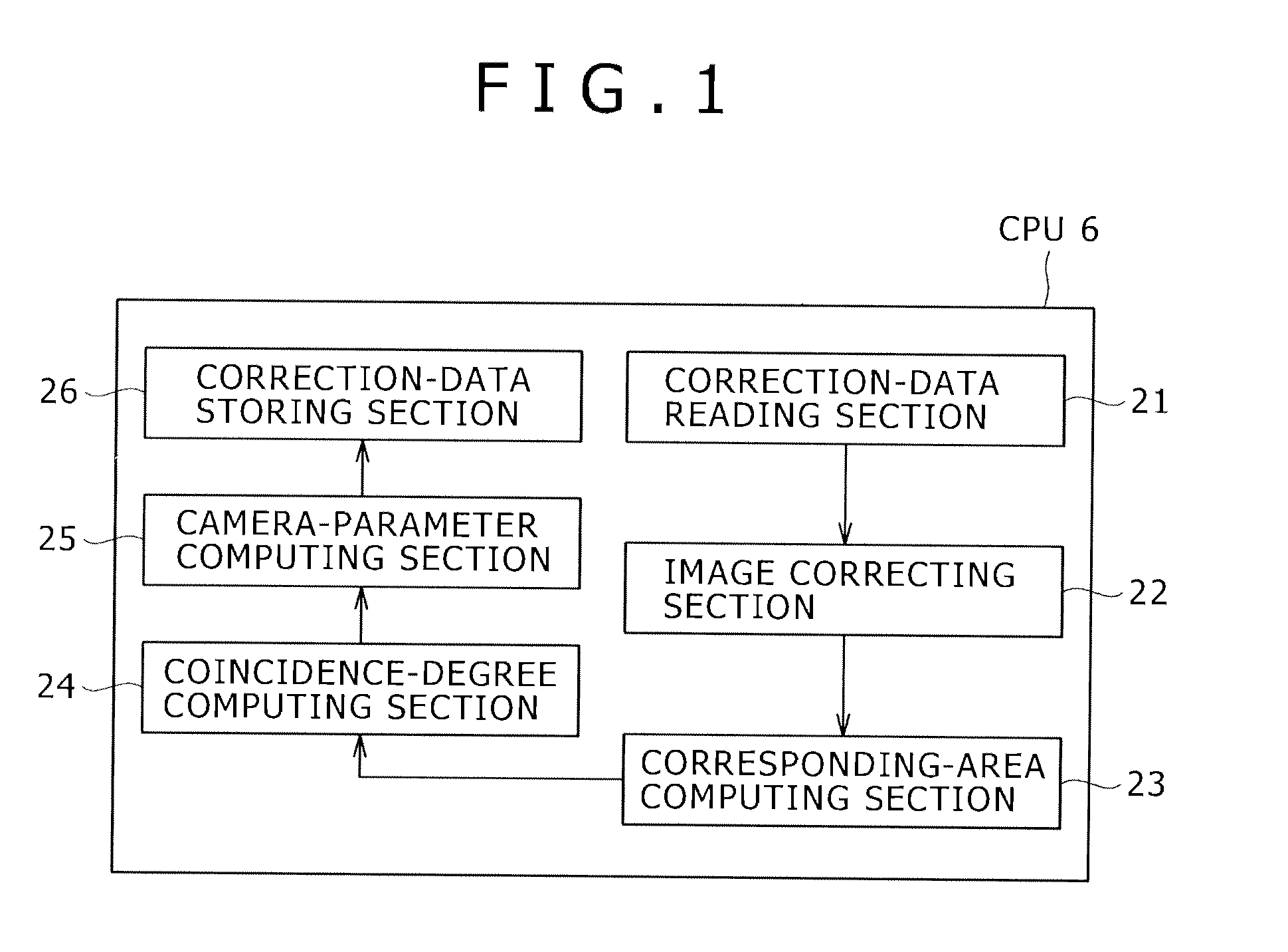
[0041]FIG. 1 is a block diagram showing a typical basic configuration of an image processing apparatus adopting a method for calibrating a camera, which serves as an imaging apparatus, in accordance with a first embodiment of the present invention. Details will be described later.

[0042]The first embodiment described below implements a method for inferring camera parameters such as external parameters, internal parameters and distortion parameters.

[0043]In this embodiment, however, a horizontal-direction scale factor and a vertical-direction scale factor which are included in the internal parameters are adjusted by adjusting a left camera with a right camera taken as a reference, adjusted by adjusting the right camera with the left camera taken as a reference or adjusted by adjusting both the left and right cameras in such a way that the scale factors of the left image become equal to the scale factors of the right image. If a object with a known size and a known distance can be phot...

second embodiment

[0133]A second embodiment is explained in detail by referring to diagrams as follows.

[0134]It is to be noted that configurations included in the calibration method according to the second embodiment as configurations identical with their counterparts in the first embodiment described earlier are denoted by the same reference numerals as the counterparts in the diagrams and the identical configurations are not explained again in order to avoid duplications of descriptions.

[0135]As shown in FIG. 5, the second embodiment is configured to implement a vehicle onboard system comprising a control unit 2 in addition to the camera unit 1 serving as an imaging apparatus. In the following description explaining a typical configuration, it is assumed that the cameras 4a and 4b are installed typically in a vehicle to take images of a object in front of the vehicle. However, the cameras 4a and 4b are installed not necessarily in a vehicle but they can be installed in a building or the like.

[0136]...

third embodiment

[0174]A third embodiment is explained in detail by referring to diagrams as follows.

[0175]It is to be noted that configurations included in the calibration method according to the third embodiment as configurations identical with their counterparts in the first and second embodiments described earlier are denoted by the same reference numerals as the counterparts in the diagrams and the identical configurations are not explained again in order to avoid duplications of descriptions.

[0176]In the third embodiment, the corresponding-area computing section 23 detects a body angle and the like as characteristic points from the right image as shown in FIG. 18 and detects these characteristic points, which have been detected from the right image, from the left image. Then, the corresponding-area computing section 23 associates each of the characteristic points detected from the right image with one of the characteristic points detected from the left image. In the example shown in FIG. 18, t...


PUM


Abstract

It is possible to provide an image processing apparatus capable of carrying out calibration easily and precisely without requiring a special facility and provide an imaging apparatus making use of the image processing apparatus. The imaging apparatus comprises at least two cameras 4a and 4b. The image processing apparatus or the image processing apparatus comprises a corresponding-area computing section 23 for finding a relation between areas on images taken by the cameras 4a and 4b; a coincidence-degree computing section 24 for finding a degree of coincidence of information obtained from corresponding areas on the images taken by the cameras 4a and 4b; and a camera-parameter computing section 25 for finding camera parameters on the basis of the coincidence degree computed by the coincidence-degree computing section 24.

Description

TECHNICAL FIELD[0001]The present invention relates to an image processing apparatus for carrying out calibration of an imaging apparatus and relates to the imaging apparatus making use of the image processing apparatus.BACKGROUND ART[0002]In recent years, a obstacle detecting apparatus for detecting obstacles such as a pedestrian, a vehicle by using cameras is put to practical use. A stereo camera is an apparatus for computing the disparity of the same object on a plurality of images, which are taken at the same time, by adoption of a template matching technique and for computing the position of the object in a real space by adoption of a known conversion formula on the basis of the computed disparity.[0003]The stereo camera computes the distance of a object by making use of a pair of images taken by utilizing two imaging apparatus. A stereo-camera apparatus for recognizing a object can be applied to a system such as a monitoring system for detecting an intrusion of a suspicious ind...

Claims


Application Information

Patent Timeline
IPC IPC(8): G01B11/14
CPCH04N13/0246H04N17/002G06T7/002G06T2207/30256G01B11/14H04N13/0022H04N2013/0081G06T2207/30261G06T7/85H04N13/246H04N13/128
Inventor HIGUCHI, MIRAISAKANO, MORIHIKOSHIMA, TAKESHIMURAMATSU, SHOJIMONJI, TATSUHIKO
Owner HITACHI AUTOMOTIVE SYST LTD
Why Eureka
Try Eureka