Supercharge Your Innovation With Domain-Expert AI Agents!

Optical module mounting unit and optical module

a technology for mounting units and optical modules, applied in optical elements, semiconductor lasers, instruments, etc., can solve the problems of difficult cost reduction, affecting the yield ratio of optical modules, and the inability to remove the optical module from the electronic substrate, so as to reduce the cost of production and reduce the cost. , the effect of maximizing the utilization of module properties

Active Publication Date: 2013-06-13
FURUKAWA ELECTRIC CO LTD
View PDF0 Cites 5 Cited by
  • Summary
  • Abstract
  • Description
  • Claims
  • Application Information

AI Technical Summary

Benefits of technology

This solution improves yield ratios, reduces manufacturing costs, and allows for efficient module upgrades and replacements, minimizing damage and enhancing system flexibility in high-density signal transmission applications.

Problems solved by technology

Since the optical module is conventionally mounted on the electronic substrate by bonding, as described above, the optical module is not removable from the electronic substrate.
However, if very high reliability is required for the optical module, a yield ratio in manufacturing the optical modules decreases remarkably, and cost reduction becomes difficult.
If bonding defect or failure occurs in the optical module, the whole electronic substrate on which the optical modules are mounted needs to be replaced.

Method used


Image

  • Optical module mounting unit and optical module
  • Optical module mounting unit and optical module
  • Optical module mounting unit and optical module

Examples


Embodiment Construction

[0040]Exemplary embodiments of the present invention are described in detail below with reference to accompanying drawings.

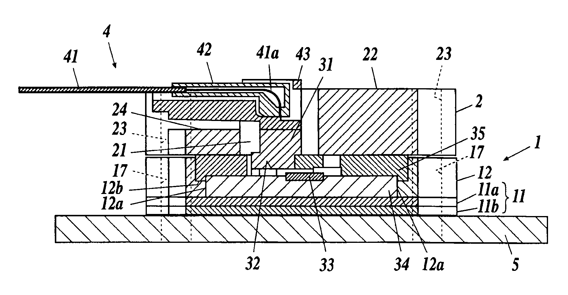
[0041]The present embodiment explains about the case of mounting an optical module on an electronic substrate by using an optical module mounting unit according to the present invention when achieving an optical interconnection between electronic substrates (boards) of a system apparatus such as a computer. In this case, since it is desirable that a space in a vertical direction with respect to the electronic substrate is small for the miniaturization of the system apparatus, an optical waveguide which is optically interconnected to the optical module is arranged parallel to the electronic substrate.

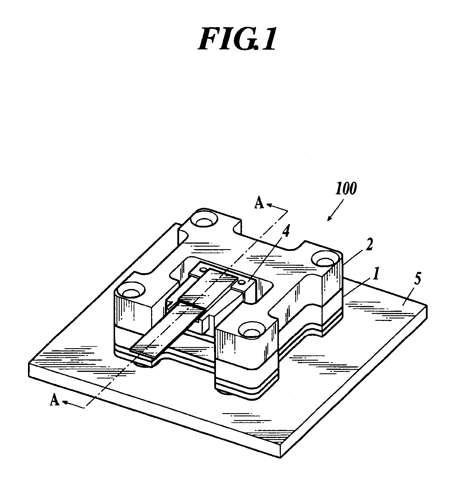
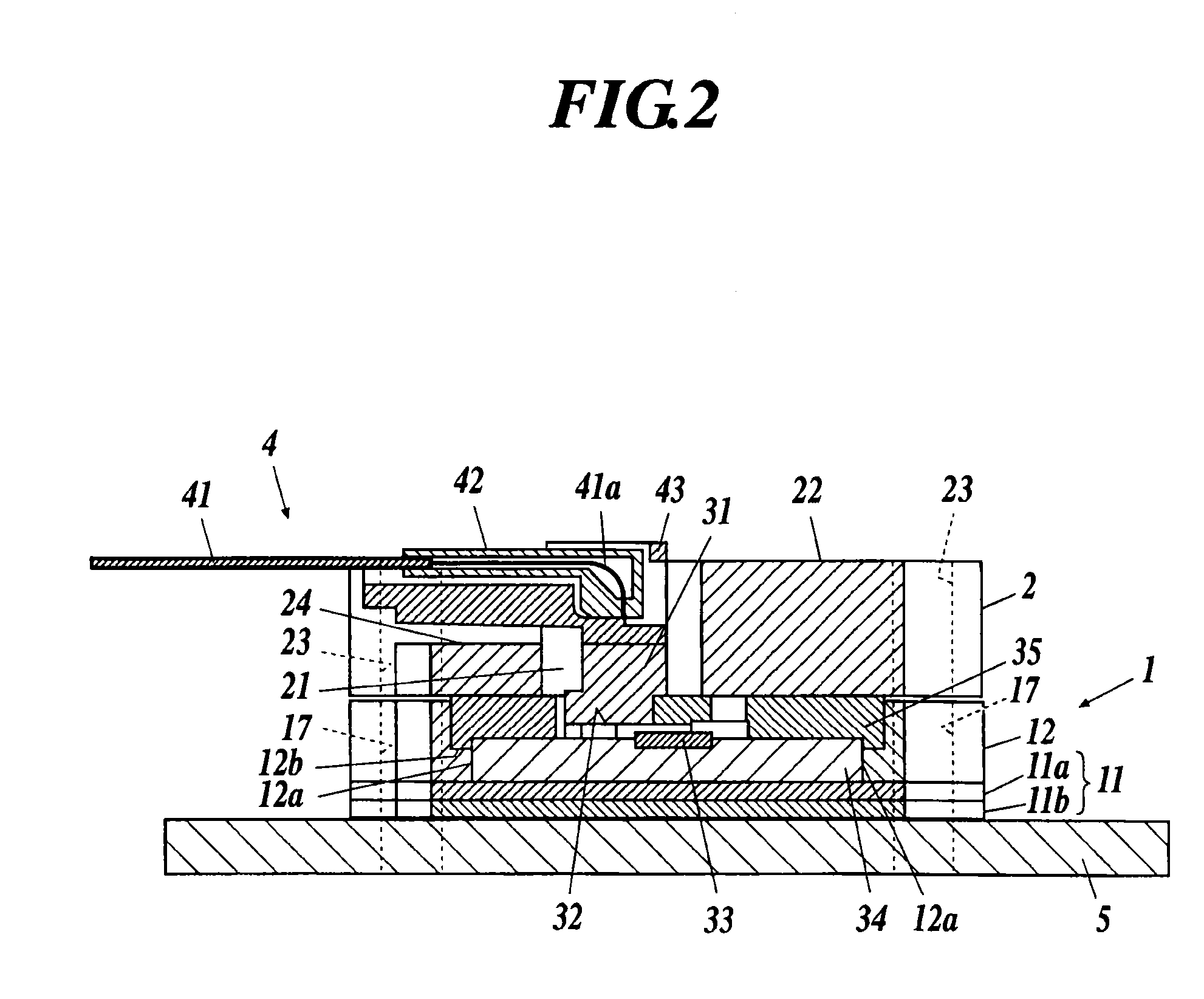
[0042]FIG. 1 is a perspective view of a mounted state of an optical module according to the present embodiment, FIG. 2 is a cross section taken along a line A-A in FIG. 1, and FIG. 3 is an exploded perspective view of FIG. 1. FIG. 4 is a perspective view of an electr...


PUM


Abstract

An optical module includes a module housing body including an electrical connection section for electrically connecting the electronic substrate and the optical module to each other and a housing section for housing the optical module, where the module housing body is mounted on the electronic substrate in such a manner that an electrical connection terminal of the electronic substrate and the electrical connection section is connected to each other and a fixing member for maintaining a state in which an electrical connection terminal of the optical module has contact with the electrical connection section in the module housing body. The optical module is housed in the housing section and is fixed in a removable manner by the fixing member, and the optical waveguide and the optical element are configured to be optically coupled to each other in a state in which the optical module is fixed.

Description

CROSS-REFERENCE TO RELATED APPLICATIONS [0001]This application is a continuation of and is based upon and claims the benefit of priority under 35 U.S.C. §120 for U.S. Ser. No. 12 / 937,663, filed Oct. 13, 2010 the entire contents of which is incorporated herein by reference. U.S. Ser. No. 12 / 937,663 is the national stage of PCT / JP2009 / 057426, filed Apr. 13, 2009 and claims the benefit of priority under 35 U.S.C. §119 from Japanese Patent Application No. 2008-104772, filed Apr. 14, 2008.TECHNICAL FIELD [0002]The present invention relates to an optical module mounting unit and an optical module, and more particularly, to a technique useful in mounting an optical module on an electronic substrate.BACKGROUND ART [0003]In recent years, a high-end system apparatus such as a supercomputer tends to achieve development of large-capacity and high-speed information communication by parallel operation of a plurality of CPUs, and large-capacity, high-speed, and high-density signal transmission bet...

Claims


Application Information

Patent Timeline
Patent Type & Authority Applications(United States)
IPC IPC(8): G02B6/42
CPCG02B6/4201G02B6/4214G02B6/4249G02B6/4284H01S5/02248H01S5/02284H01S5/06226H01L31/0203H01S5/02251H01S5/02325
Inventor NEKADO, YOSHINOBUNASU, HIDEYUKI
Owner FURUKAWA ELECTRIC CO LTD
Features
  • R&D
  • Intellectual Property
  • Life Sciences
  • Materials
  • Tech Scout
  • Unparalleled Data Quality
  • Higher Quality Content
  • 60% Fewer Hallucinations
Learn More