Barometric relief air zone damper

a damper and barometric relief technology, applied in the field of heat, ventilation and air conditioning, can solve the problems of increasing noise and drafts, inefficient energy consumption, and expensive ways to solve problems, and achieve the effects of reducing the size of damper inventory, reducing drafts and air noise, and reducing coil freeze up

Inactive Publication Date: 2013-06-13
CONTROLLED HLDG
View PDF63 Cites 7 Cited by
  • Summary
  • Abstract
  • Description
  • Claims
  • Application Information

AI Technical Summary

Benefits of technology

[0010]A feature of the disclosed zone dampers is the inclusion of barometrically responsive portions that effectively eliminate the need for any bypass damper system and hence reduce the size of damper inventory. An advantage of the disclosed zone dampers is a reduction in drafts and air noise, and a reduction in coil freeze up, with a resulting increase in system energy efficiency.

Problems solved by technology

This rise in static duct pressure can result in an increase in noise and drafts due, in part, to an increase in air flow velocity though the ducts in zones still calling for conditioned air.
This implementation has the disadvantage of being energy inefficient, and hence an expensive way to solve the problem.
Bypass dampers can also be expensive to install and difficult to setup.

Method used


Image

  • Barometric relief air zone damper
  • Barometric relief air zone damper
  • Barometric relief air zone damper

Examples


Embodiment Construction

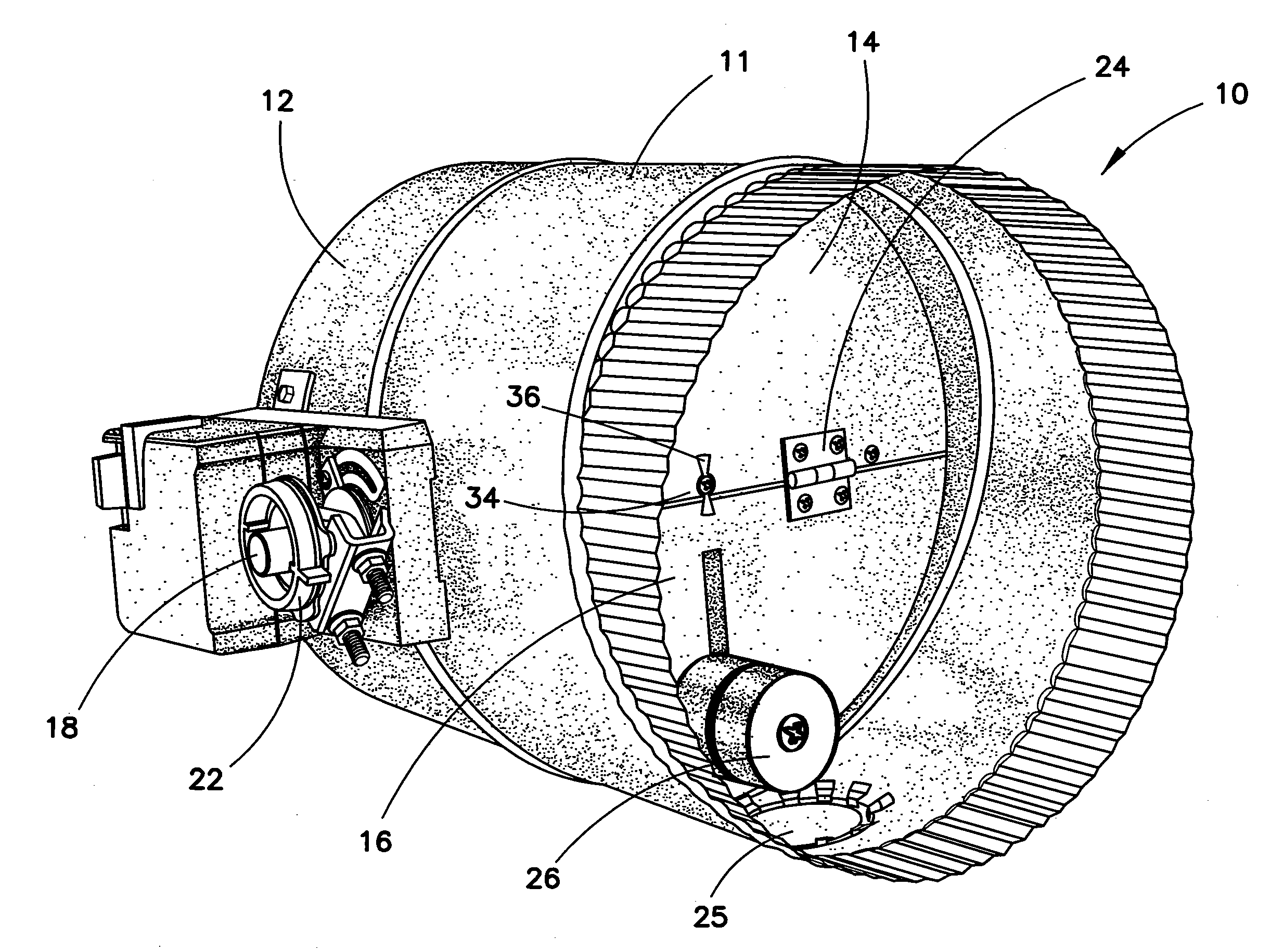
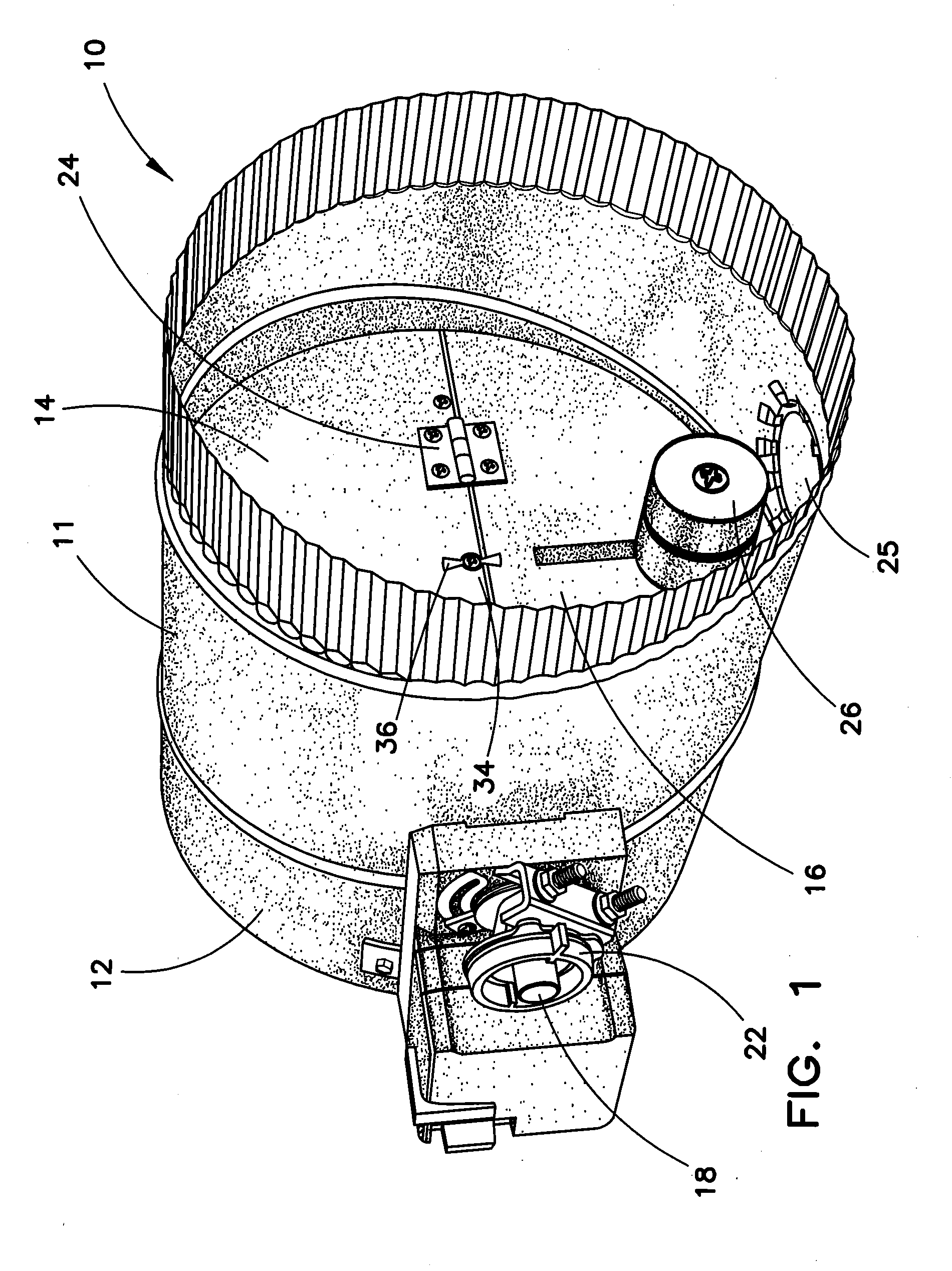
[0024]FIG. 1 shows a barometrically responsive zone damper 10 positioned within a segment of ducting 11, which forms a damper shell 12. The damper 10 can include an upper portion 14 and a lower portion 16. The upper portion 14 can be fixed to a shaft 18 mounted in bushings fixed in the shell 12, the shaft 18 extending through the shell 12. The position of the shaft 18 and upper portion 14 of the zone damper 10 can be controlled by a damper actuator 22 that can be located on the outside or inside of the shell 12. The damper actuator 22 can be situated on either side of the shell 12 and controlled by a zone thermostat, not shown. The lower portion 16 of the zone damper 10 is connected to the upper portion 14 of the damper by a hinge 24 to permit independent movement of the lower portion 16 relative to the upper portion 14. In the absence of a sufficient air pressure differential or air flow through the ducting 11, the force of gravity will cause the lower portion 16 to pivot to a posi...


PUM


Abstract

A zone damper having a first portion responsive to the static pressure in a HVAC system to open and bleed an amount of conditioned air past the damper when the static pressure of the system increases above a selected level, a second portion controlled by a actuator to move between an open and a closed position in response to a zone thermostat, and a coupling mechanism coupling the first and second portions to limit the relative movements of the two portions with respect to each other, and a biasing mechanism exerting a torque against the system static pressure differential. The first portion can be a single one-piece undivided blade pivotally mounted with a shell surrounding the zone damper.

Description

CROSS-REFERENCE TO RELATED APPLICATION[0001]This application is a continuation-in-part of U.S. Ser. No. 13 / 463,952 filed May 4, 2012, which in turn is related to and claims all benefit of U.S. Provisional Application Ser. No. 61 / 569,845 filed Dec. 13, 2011.BACKGROUND[0002]This invention relates to heating, ventilating and air conditioning (“HVAC”) systems that include at least two zones controlled by sensors, generally thermostats, located within the at least two zones that control corresponding dampers in ducts leading from usually a single HVAC source to the at least two zones.[0003]In a conventional HAVC zoning system, conditioned air can be supplied to a plurality of zones, each zone being controlled by its own thermostat. Zoning systems for such an HVAC system typically includes zone dampers disposed in the ductwork for controlling the air flow of the conditioned air to the zones in response to the thermostat. These zoning systems control the flow of conditioned air to the plur...

Claims


Application Information

Patent Timeline
Patent Type & Authority Applications(United States)
IPC IPC(8): F24F11/053F24F11/04F24F11/76
CPCF24F11/04F24F13/1426F24F11/053F24F11/74F24F11/76Y10T137/0352F24F13/24
Inventor JACKSON, RONALD E.
Owner CONTROLLED HLDG
Why Eureka
Try Eureka