Tester apparatus for obtaining forming limit diagram

Active Publication Date: 2013-06-20
SAMSUNG ELECTRONICS CO LTD
View PDF16 Cites 15 Cited by
  • Summary
  • Abstract
  • Description
  • Claims
  • Application Information

AI Technical Summary

Benefits of technology

[0009]Therefore, it is an aspect of the present disclosure to provide a tester apparatus for obtaining a

Problems solved by technology

However, if the FLD test is conducted in a general press facility without having an exclusive test apparatus configured to obtain the forming limit diagram,

Method used


Image

  • Tester apparatus for obtaining forming limit diagram
  • Tester apparatus for obtaining forming limit diagram
  • Tester apparatus for obtaining forming limit diagram

Examples


Embodiment Construction

[0036]Reference will now be made in detail to the embodiments of the present disclosure, examples of which are illustrated in the accompanying drawings, wherein like reference numerals refer to like elements throughout.

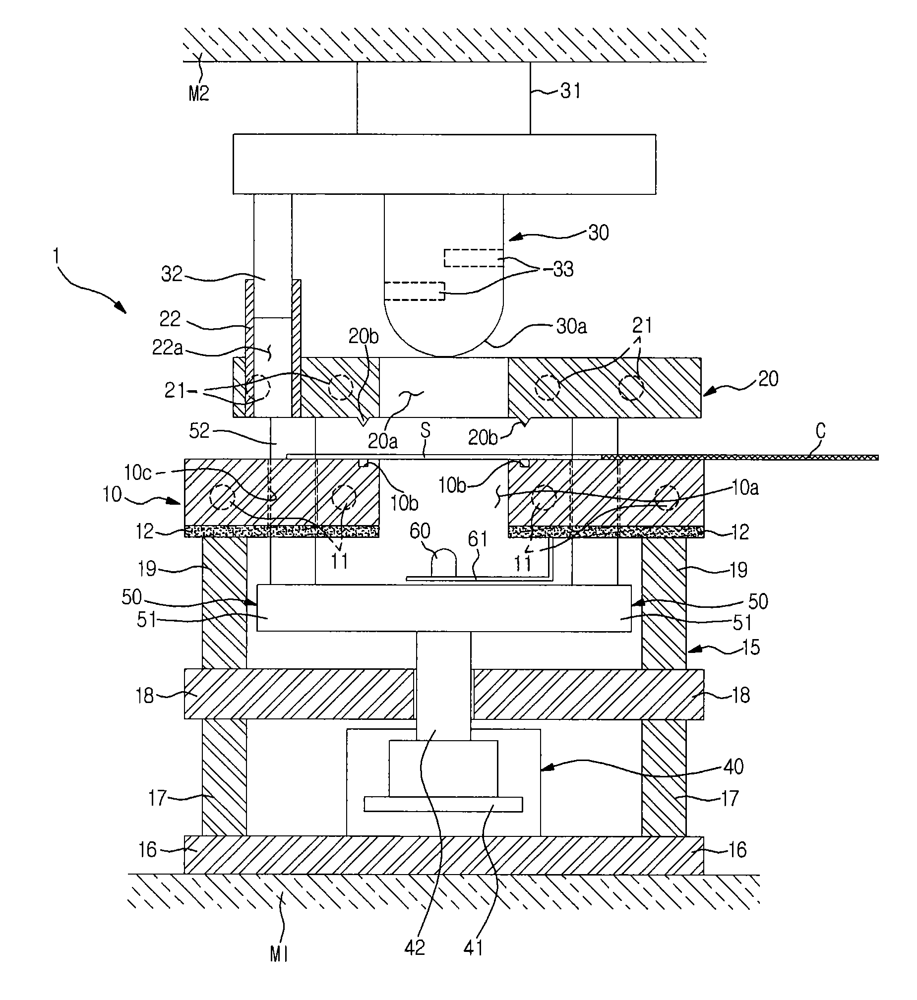
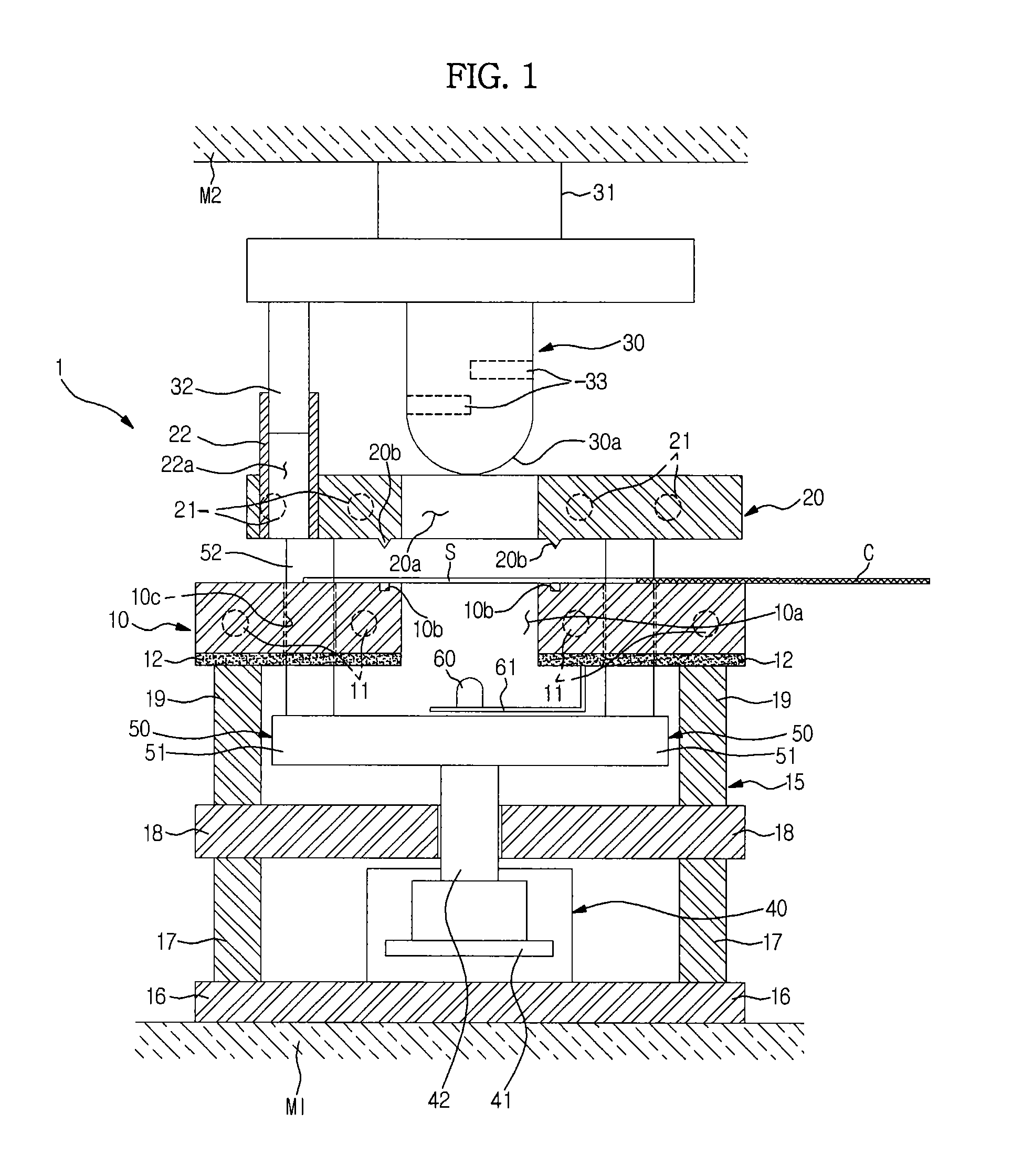
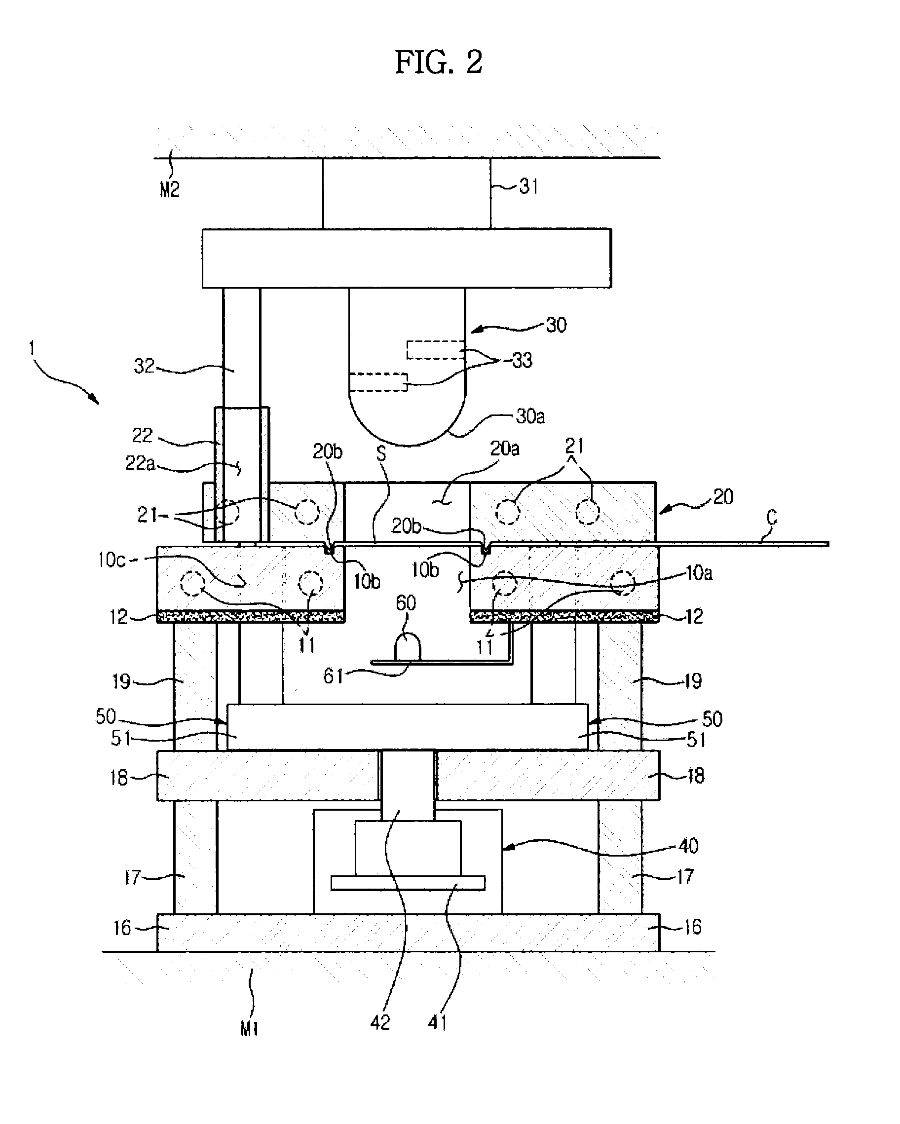
[0037]As illustrated in FIG. 1, a tester apparatus used to obtain a forming limit diagram 1 includes a fixing jig 10 and a mobile jig 20 that are configured to fix a sample ‘S’, a punch 30 configured to apply pressure and perform a forming on the sample ‘S’, a driving apparatus 40 configured to drive the mobile jig 20 to be moved in a vertical direction, and an interlocking apparatus 50 configured to connect in between the mobile jig 20 and the driving apparatus 40. The sample ‘S’ may be sheet metal or a other metallic panel, for example. However, sample ‘S’ may comprise other materials which may be tested and need not be limited to sheet metal or metallic panels.

[0038]The fixing jig 10 is formed in a plate type, and a processing hole 10a may be formed at a central po...


PUM

PropertyMeasurementUnit
Temperatureaaaaaaaaaa

Abstract

A tester apparatus capable of obtaining a forming limit diagram pertaining to a sample having a high degree of precision includes a fixing jig and a mobile jig installed at an upper side of the fixing jig so as to enable a vertical movement. The mobile jig may be configured to fix the sample in cooperation with the fixing jig, and a driving apparatus disposed at a lower side of the fixing jig may be configured to drive the vertical movement of the mobile jig. An interlocking apparatus provided in between the mobile jig and the driving apparatus may be configured to deliver a driving force of the driving apparatus to the mobile jig.

Description

CROSS-REFERENCE TO RELATED APPLICATIONS[0001]This application claims the priority benefit of Korean Patent Application No. 10-2011-0135311, filed on Dec. 15, 2011, in the Korean Intellectual Property Office, the disclosure of which is incorporated herein by reference.BACKGROUND[0002]1. Field[0003]Embodiments disclosed herein relate to a tester apparatus for obtaining a forming limit diagram from basic physical properties of a sample which is a forming material.[0004]2. Description of the Related Art[0005]Recently, when developing a product, CAM (Computer Aided Manufacturing) applications in mold design are increasingly used to reduce a production time of the product and to respond to the diversification of the product lineups.[0006]CAM applications in mold design may be used during the production process of a product and enable the confirmation and the modification of a process result prior to the production of a product. Additionally, when changing the design of a product, CAM appl...

Claims


Application Information

Patent Timeline
IPC IPC(8): G06F17/50
CPCB21D22/02G06F17/5086G01N3/08G06F2217/41G01N3/04Y02T10/82G06F2113/22G01N3/20G06F30/17
Inventor NAM, KI JULEE, JUN BEOMCHO, YONG KYUN
Owner SAMSUNG ELECTRONICS CO LTD
Why Eureka
Try Eureka