Continuously variable dynamic brake for a locomotive

a dynamic brake and continuous variable technology, applied in the direction of motor/generator/converter stopper, dynamo-electric converter control, electric devices, etc., can solve the problems of requiring more frequent repairs of the braking system, unable to operate the dynamic braking system, and unnecessary wear on these parts, so as to reduce the effective resistance of the grid resistor

Active Publication Date: 2013-06-20
PROGRESS RAIL SERVICES
View PDF13 Cites 5 Cited by
  • Summary
  • Abstract
  • Description
  • Claims
  • Application Information

AI Technical Summary

Benefits of technology

[0009]In accordance with another aspect, the present disclosure is directed to a method of controlling an armature chopper arranged in series with an armature and in parallel with a grid resistor to decrease the effective resistance of the grid resistor when the armature is generating current. The method may include monitoring a field current associated with a field winding, the field winding arranged in parallel with the grid resistor and the armature. The method may also include comparing the field current with a threshold value. When the field current exceeds the threshold value, the method may include calculating a duty cycle associated with the armature chopper and switching the armature chopper at the calculated duty cycle to selectively bypass the grid resistor during the portion of a period the armature chopper is on.

Problems solved by technology

First, these dynamic braking systems could not operate at slow locomotive speeds. Early braking systems could not shunt out the entire grid resistor without disconnecting the grid blower, a necessary component for dynamic braking, which is in the same circuit as the grid resistor. Typically, once the locomotive has reached speeds of 6 mph or slower, the locomotive must rely solely on its mechanical braking components, like pneumatic brakes, until the locomotive has completely stopped. The increased use of friction-based braking systems produces unnecessary wear on these parts and requires more frequent repairs of the braking system. Thus, to increase the working life of the locomotive's mechanical braking components, an extended range dynamic braking system may be required.
Second, early rheostatic braking systems are only capable of extended range dynamic braking, and cannot produce a continuously linear braking force. Extended-range dynamic braking shorts out portions of the grid resistor at a series of discrete points, such that lowering the equivalent resistance of the grid resistor is accomplished in a series of steps. In a legacy system, each step down causes locomotive handling problems for the operator. During a step-down of the grid resistor, the locomotive often lurches or lunges. The operator must be able to handle each of these difficulties to safely control the locomotive. A braking system capable of applying a continuously linear braking force is able to gradually decrease the equivalent resistance of the grid resistor, eliminating the locomotive handling problems associated with step-down dynamic braking. Thus, to increase locomotive safety, a continuously variable dynamic braking system may be required.
For example, these instabilities can create a positive feedback condition across the field coils, which will cause a runaway current build-up if not properly controlled.
Furthermore, the system cannot isolate the grid resistor in the event it malfunctions.
While the '315 publication purportedly allows for dynamic braking at low speeds, the design makes the traction motor drive system unnecessarily vulnerable to current instability and grid resistor breakage.

Method used


Image

  • Continuously variable dynamic brake for a locomotive
  • Continuously variable dynamic brake for a locomotive
  • Continuously variable dynamic brake for a locomotive

Examples


Embodiment Construction

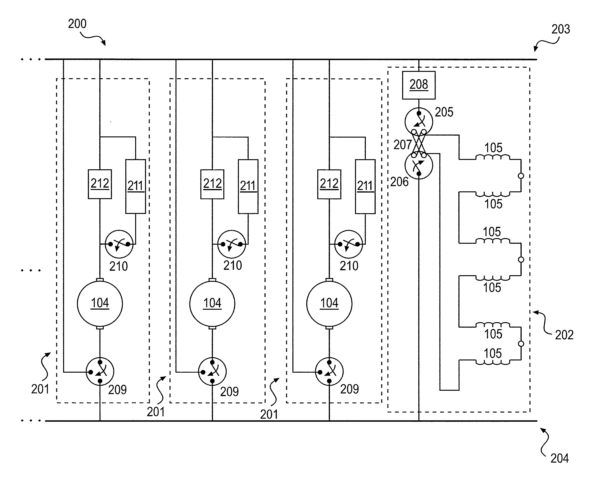
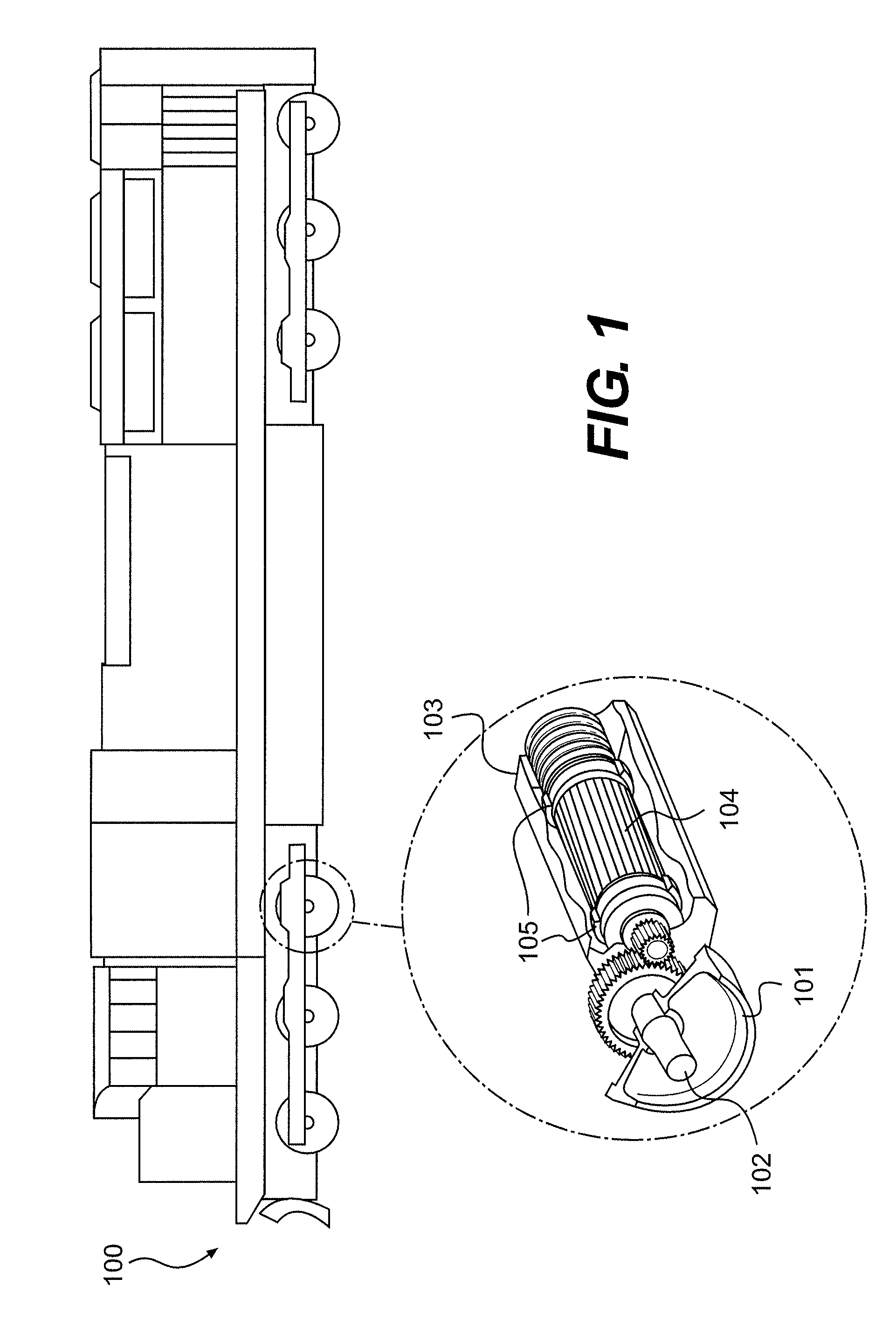
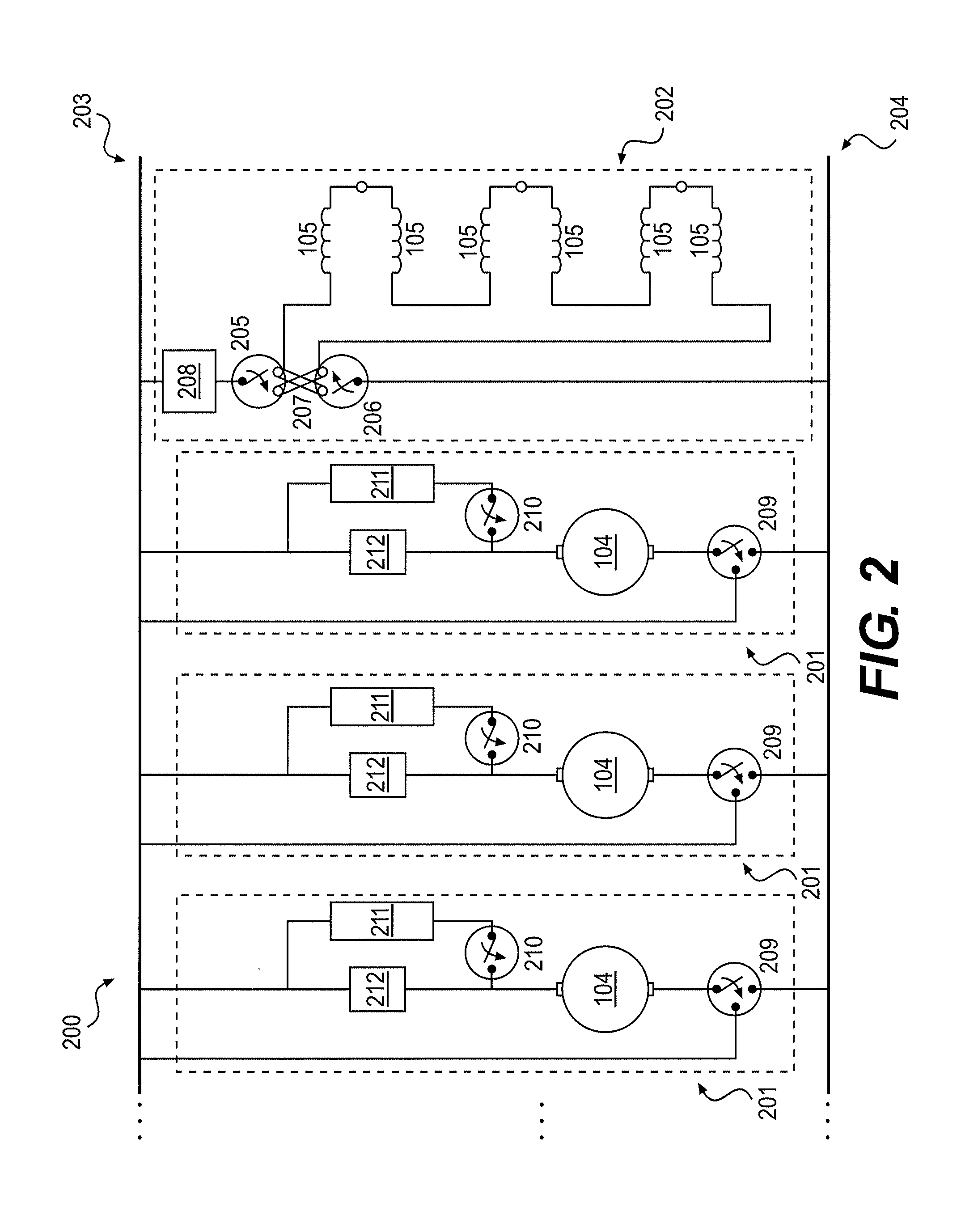
[0015]FIG. 1 illustrates an exemplary locomotive 100 in which systems and methods for dynamic braking may be implemented consistent with the disclosed embodiments. Locomotive 100 may be any electrically powered rail vehicle employing DC traction motors for propulsion. Furthermore, any electrically powered vehicle employing DC traction motors for propulsion could also incorporate the systems and methods for traction motor isolation consistent with the disclosed embodiments. According to the exemplary embodiment illustrated in FIG. 1, locomotive 100 may include six pairs of wheels 101, with each pair of wheels 101 attached to an axle 102 that is rotatably coupled to a traction motor 103. Traction motors 103 may each include an armature 104 and a field winding 105. As locomotive 100 uses a DC traction motor system, traction motor 103 may comprise separate circuits for armature 104 and field winding 105. FIG. 2 illustrates the relationship between armature 104 and field winding 105 with...


PUM


Abstract

This disclosure is directed to a traction motor drive system. The traction motor drive system may include a field winding subsystem comprising a field winding associated with a traction motor. The traction motor drive system may also include an armature subsystem arranged in parallel with the field winding subsystem. The armature subsystem may include an armature having first and second armature terminals and a grid resistor selectively electrically coupled in series with the armature. The armature subsystem may also include an armature chopper arranged in parallel with the grid resistor and electrically coupled in series with the armature. The armature chopper may be configured, when the grid resistor is electrically coupled to the armature, to conditionally conduct current to the armature.

Description

TECHNICAL FIELD[0001]The present disclosure relates generally to traction motor drive systems, and more particularly, to systems and methods for dynamic braking on a locomotive.BACKGROUND[0002]During dynamic braking, traction motors may function as generators to slow the movement of the locomotive by converting the kinetic energy of the locomotive into electrical energy. In rheostatic dynamic braking, grid resistors can be incorporated to dissipate the generated energy as heat. As the locomotive slows, the current generation of the armature decreases. To allow dynamic braking to continue as current generation of the armature continues to decrease, the field current is increased towards the maximum rated current of the field windings. Once the maximum rating of the field current is reached, the equivalent resistance of the grid resistor must be decreased for dynamic braking to continue to function. Lowering the equivalent resistance of the grid resistors permits dynamic braking despi...

Claims


Application Information

Patent Timeline
Patent Type & Authority Applications(United States)
IPC IPC(8): B61C3/00H02P3/12
CPCB60L3/0061B60L3/0076B60L3/04B60L7/04B60L7/08B60L2200/26B60L2210/10B60L2220/20B60L2220/42Y02T10/7216Y02T10/648H02P3/12Y02T10/64Y02T10/72
Inventor KRAL, JOHN FRANKLINBELTRAMIN, SIDARTA FORNARI
Owner PROGRESS RAIL SERVICES
Why Eureka
Try Eureka