Heat cooker

a technology of heat cooker and heating compartment, which is applied in the field of heat cooker, can solve the problems of difficult to dilute smoke and clearly viewable smoke, the temperature decline in the heating compartment can be suppressed, and the smoke or steam filled in the heating compartment is blown off, so as to reduce prevent the filling of smoke in the heating compartment. , the effect of reducing the time required for heat cooking

Active Publication Date: 2013-06-20
SHARP KK
View PDF34 Cites 10 Cited by
  • Summary
  • Abstract
  • Description
  • Claims
  • Application Information

AI Technical Summary

Benefits of technology

[0022]Further, since discharging of the smoke in the heating compartment is started during the heat cooking of the heating object, filling of smoke in the heating compartment can be prevented at an end of the heat cooking.
[0023]Then, since the openness of the air supply opening during the heat cooking of the heating object is smaller than the openness of the air supply opening after an end of the heat cooking of the heating object, no large amount of outside air flows through the air supply opening into the heating compartment, so that discharge of high-temperature air in the heating compartment out of the casing is prevented. Thus, temperature declines in the heating compartment can be suppressed, and the time required for heat cooking can be shortened.
[0048]According to the heat cooker of the invention, the control unit controls operation of the variable-type air supply opening so that the openness of the air supply opening becomes a predetermined target openness larger than 0% during heat cooking of a heating object, and further controls operation of the variable-type air supply opening so that the openness of the air supply opening becomes larger than the target openness at an end of the heat cooking of the heating object. Thus, a proper quantity of air supply into the heating compartment is exerted during heat cooking of the heating object, so that the smoke in the heating compartment can be gradually pushed out of the casing. Therefore, during the heat cooking of the heating object, the smoke discharged from within the heating compartment out of the casing can be kept unnoticeable.
[0050]Therefore, even after an end of the heat cooking, smoke discharged from within the heating compartment out of the casing can be kept unnoticeable.

Problems solved by technology

However, in this conventional heat cooker, since the exhaust fan is driven after completion of heat cooking of the heating object, the smoke or steam filled in the heating compartment is blown off at a burst from the exhaust opening.
As a result, there has been an issue that smoke or steam discharged from within the heating compartment after completion of heat cooking of the heating object becomes noticeable.
In such a case, merging an exhaust air stream going out of the heating compartment with other air streams indeed allows the steam to be diluted so as to become less noticeable to some degree, but the smoke is hard to dilute and clearly viewable.

Method used


Image

  • Heat cooker
  • Heat cooker
  • Heat cooker

Examples


Embodiment Construction

[0067]Hereinbelow, a heat cooker of the present invention will be described in detail by embodiments thereof illustrated in the accompanying drawings.

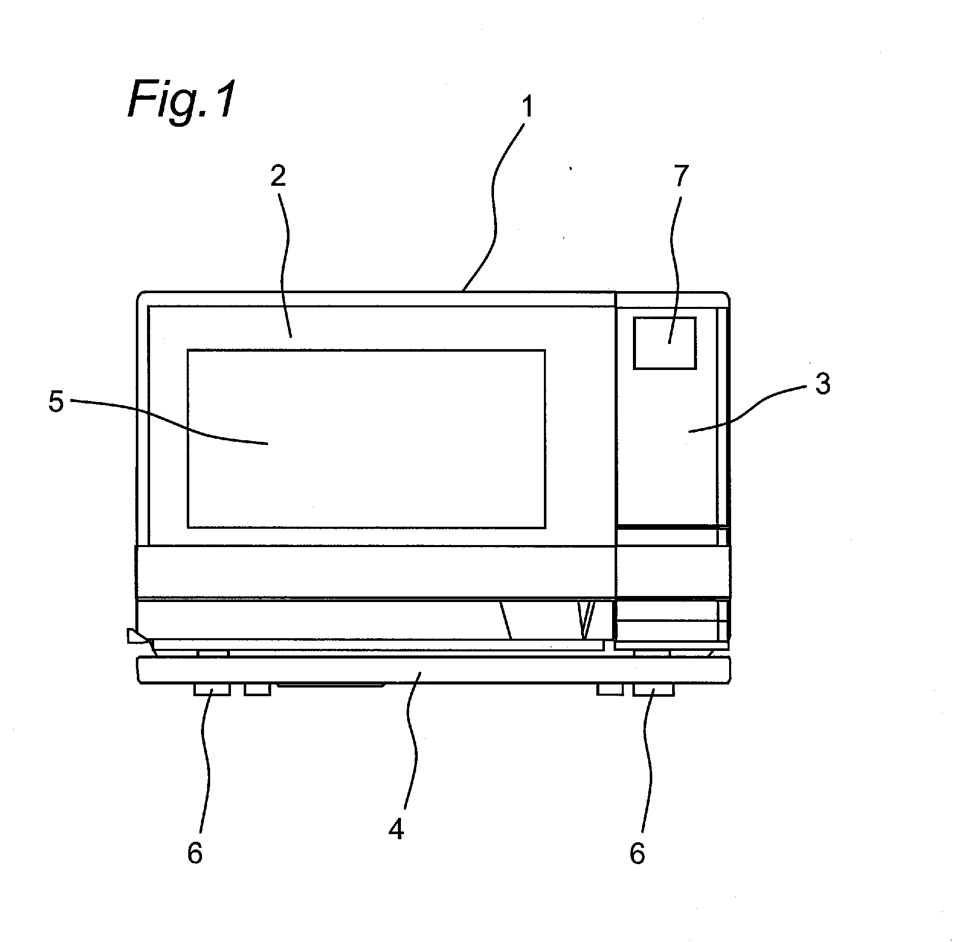
[0068]FIG. 1 is a front view of a heat cooker according to an embodiment of the invention.

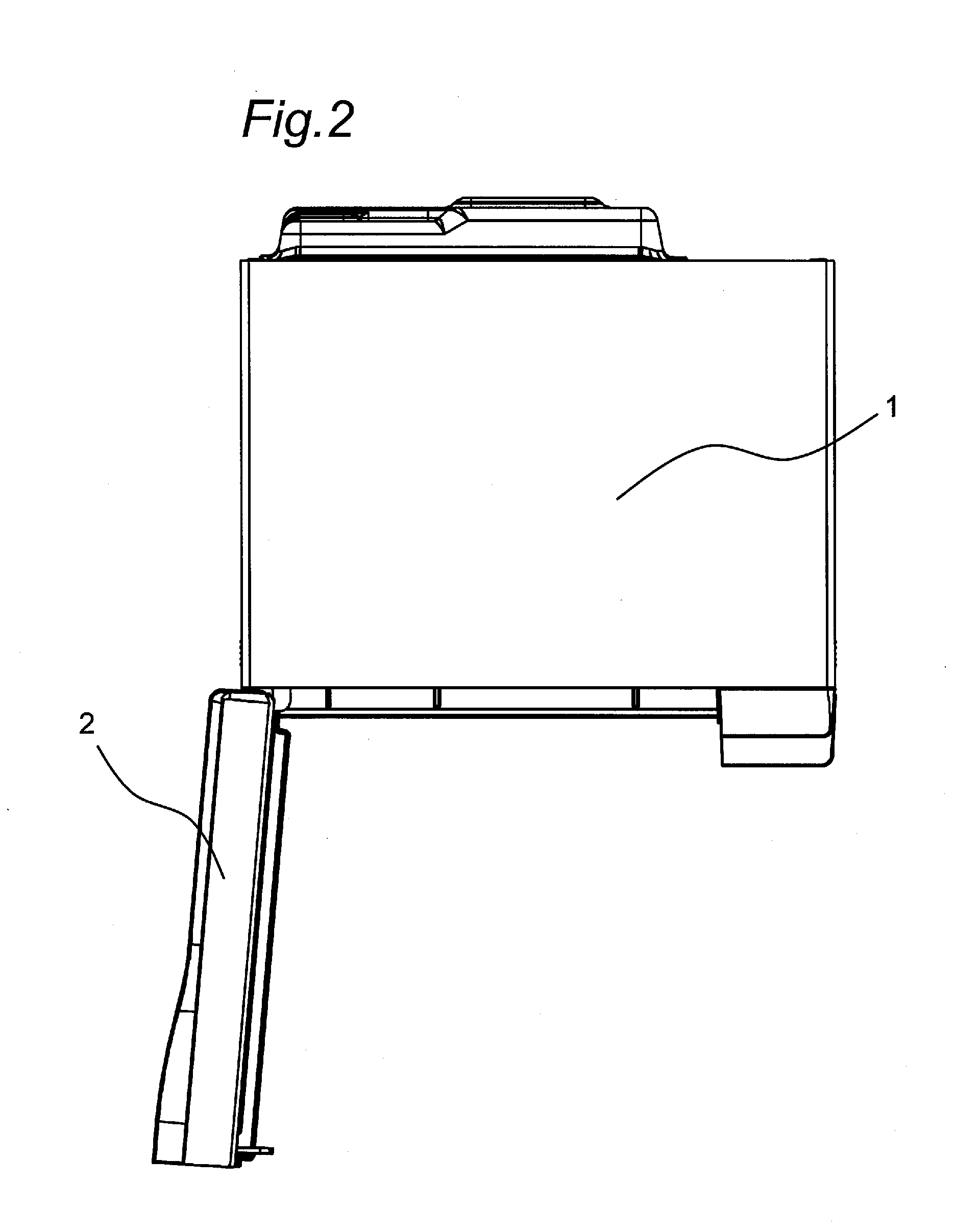
[0069]The heat cooker includes a casing 1, and a handle-attached door 2 as an example of a door fitted on a front face side of the casing 1. A heat-resistant glass 5 is set at a generally center of the handle-attached door 2. An operation panel 3 is also provided on the front face side of the casing 1 so as to be adjacent to the closed handle-attached door 2. A dew receiving container 4 is placed below the handle-attached door 2 and the operation panel 3.

[0070]The operation panel 3 has an LCD (Liquid Crystal Display) part 7, and the LCD part 7 gives a display corresponding to each operation. Although not shown, a plurality of press buttons and the like are also provided on the operation panel 3.

[0071]The dew receiving container 4 is a container th...


PUM


Abstract

The disclosed heat cooker includes: a cooling fan for sucking in outside air from outside a casing and blowing the same into the casing during heat cooking of a heating object or item to be heated; an electrical component chamber which allows the outside air blown by the cooling fan to flow inside the casing; an air supply opening provided in a heating compartment to supply the outside air of the electrical component chamber into the heating compartment; an exhaust opening provided in the heating compartment for discharging smoke from the heating compartment to outside the heating compartment; an exhaust tube for guiding to outside of the casing the smoke that has come out of the heating compartment from the exhaust opening; an air supply damper for opening and closing the air supply opening; and a control unit (200) for controlling opening/closing operations of the air supply damper. The control unit (200) controls opening/closing operations of the air supply damper so that an openness of the air supply opening becomes a predetermined target openness larger than 0% during heat cooking of the heating object, and further controls the opening/closing operations of the air supply damper so that upon an end of heat cooking of the heating object, the openness of the air supply opening becomes larger than the target openness.

Description

TECHNICAL FIELD[0001]The present invention relates to a heat cooker.BACKGROUND ART[0002]Among conventional heat cookers is one which includes an exhaust fan for discharging smoke or steam from within a heating compartment out of the heating compartment as described in JP 2007-10189 A (PTL 1). The exhaust fan is not driven during heat cooking of a heating object, which is an item to be heated, but driven when the door of the heating compartment is opened after completion of the heat cooking of the heating object. By the drive of the exhaust fan, smoke or steam in the heating compartment is discharged outside through an exhaust opening positioned apart from the door.[0003]However, in this conventional heat cooker, since the exhaust fan is driven after completion of heat cooking of the heating object, the smoke or steam filled in the heating compartment is blown off at a burst from the exhaust opening.[0004]As a result, there has been an issue that smoke or steam discharged from within...

Claims


Application Information

Patent Timeline
Patent Type & Authority Applications(United States)
IPC IPC(8): H05B6/64H05B6/80
CPCF24C15/006F24C15/08H05B6/804H05B6/642F24C15/322
Inventor UEKI, TOSHIAKI
Owner SHARP KK
Why Eureka
Try Eureka