Encoding information in illumination patterns

Inactive Publication Date: 2013-06-20
EASTMAN KODAK CO
View PDF7 Cites 31 Cited by
  • Summary
  • Abstract
  • Description
  • Claims
  • Application Information

AI Technical Summary

Benefits of technology

The patent describes a method for creating a special light pattern that can be used to encode information on a surface. This method involves selecting the information to be encoded, identifying the unique pattern on the surface, and creating a special pattern that matches the surface pattern and the selected information. The resulting pattern can then be stored for later use. This process allows for accurate and reliable identification of information on a surface using a special light pattern.

Problems solved by technology

Automatic recognition and identification of objects, and embedding of information in objects for this purpose, are well-known problems in electronic imaging.
This is an important distinction, in that the above mentioned techniques do not, strictly speaking, verify the authenticity of the object.
The tags could in principle be placed onto unauthentic objects, or be faked by other persons familiar with barcode or RFID technology, especially because the presence of such tags is easily detectable.
Also, most tagging techniques require at least temporary modification of the object, with tags that could be perceived as extraneous, altering object appearance and aesthetics, which may be undesirable due to the size or value of the object.
In this case a special paper with the watermarks is required, which makes it more expensive.
Because the watermarks themselves are visible, they can be a target for counterfeiting attempts.
Additional disadvantages of this approach are the facts that watermarks contain a very limited amount of information and cannot be changed quickly.
Digital watermarking and steganography overcome the visibility of embedded information, and rigidity issues such that the embedded information can be decoded from the electronic file itself or after scanning the document using a computer program.
However there are several limitations of digital watermarking and steganography.
The methods can only be used for digital images and digital data, so the extraction of the information occurs via scanning printed documents or analysis of electronic files and cannot be used on other physical objects.
The amount of information in these methods is typically limited to 32- or 64 bits.
If the digital images or documents were resized or otherwise edited before printing, embedded information can be distorted and consequently inaccessible.
Although useful, this technique has serious shortcomings when considered for the authentication problem, which include: increased speed of processing at the expense of increased complexity of the hardware; the possession of the reference object is required; the properties of the object shape are not taken into account in designing the best projected pattern, which is restricted to a periodic grating; the method is not extensible to colored objects; for the method cannot be easily extended to visual (human) authentication; and the method is not easily extended to a sequence of objects.
Unlike inverse fringe projection techniques, these patterns are not adapted to reflect 3D properties of a particular static or moving object, but are used as a means to reconstruct depth maps of object surfaces.
While these approaches take into consideration 3D surface information in designing projection patterns, they cannot be directly applied for authentication problems that are based on encoding information utilizing surface, embedding information into a surface and retrieving this information as a means of authentication for a variety of products including printed documents.

Method used


Image

  • Encoding information in illumination patterns
  • Encoding information in illumination patterns
  • Encoding information in illumination patterns

Examples


Embodiment Construction

[0032]The present invention will be directed in particular to elements forming part of, or in cooperation more directly with the apparatus in accordance with the present invention. It is to be understood that elements not specifically shown or described may take various forms well known to those skilled in the art.

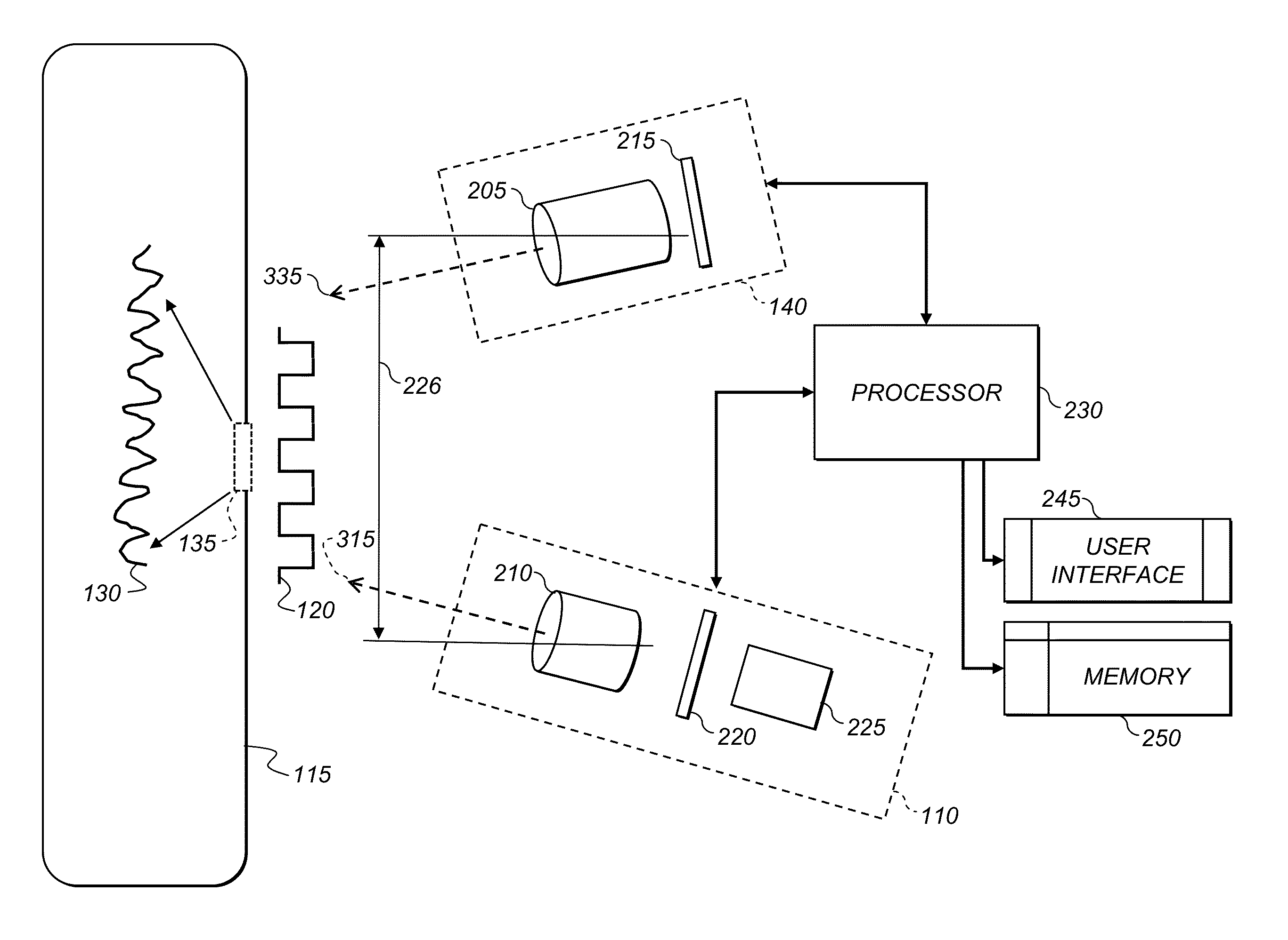
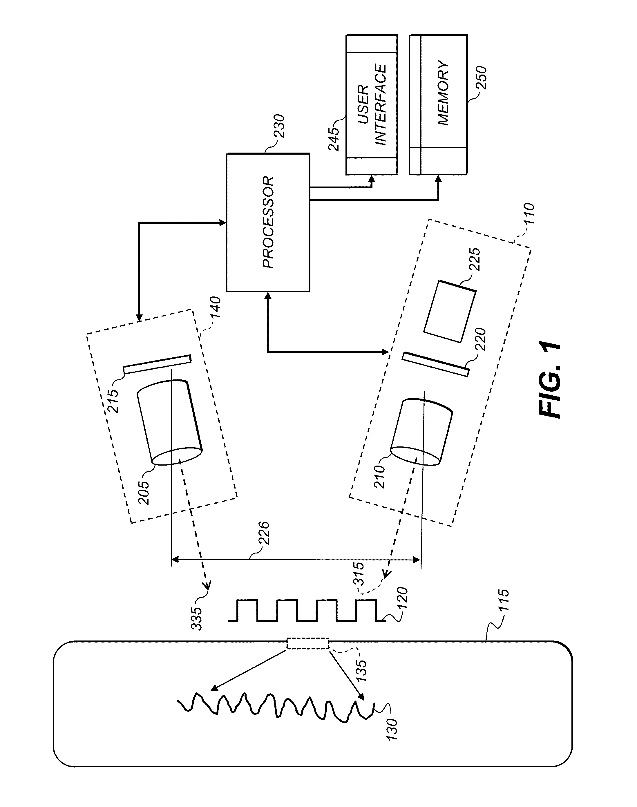
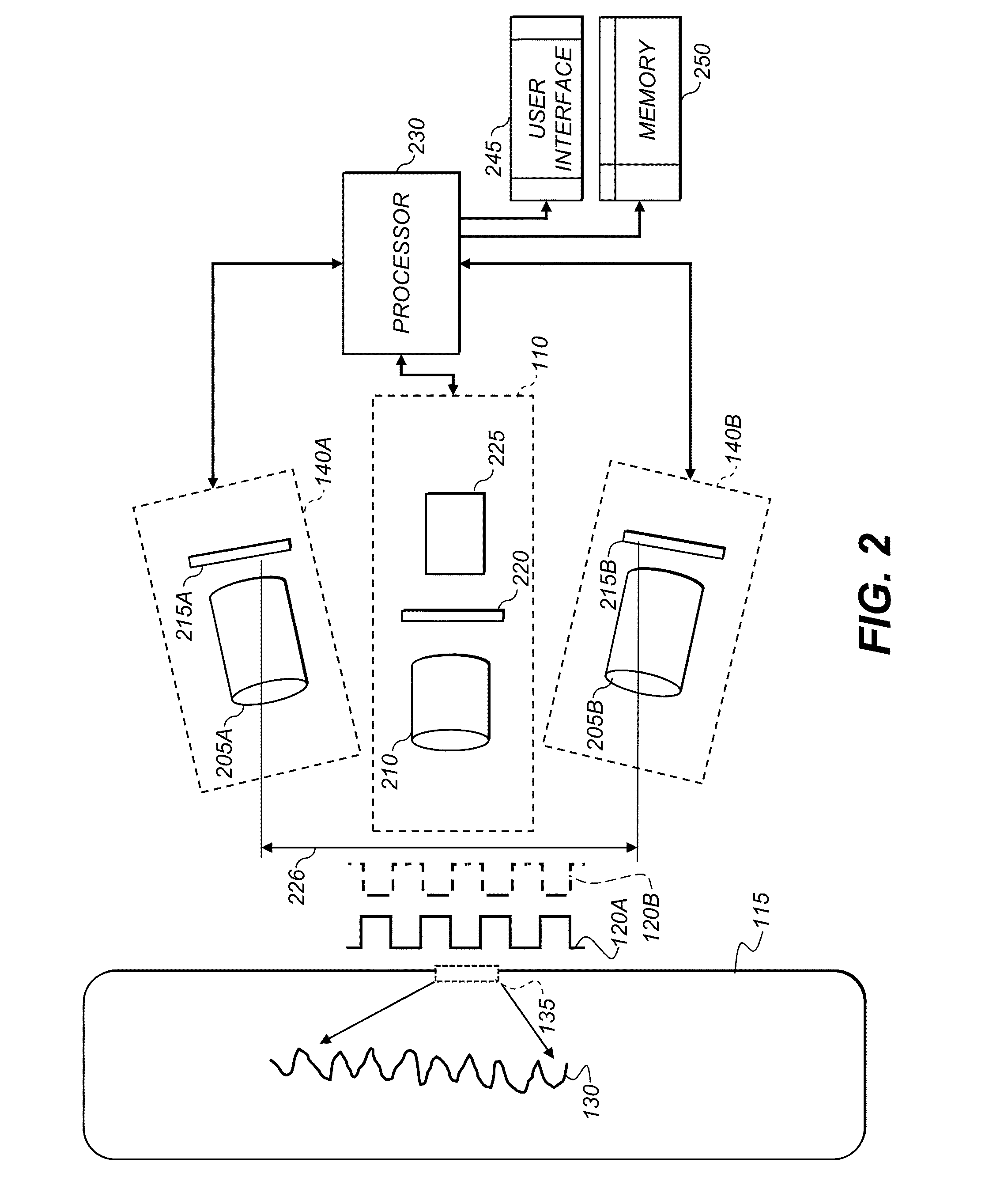
[0033]In order to ensure a robust encoding, and data retrieval that are applicable for a range of objects and items, as well as usages such as authentication, the preferred embodiment of the present invention focuses on three key elements: information to be encoded, a specified surface texture that is identified, created or modified on the surface of the object or an item, and which is used in the process of encoding, retrieving and / or decoding information, and structured light pattern, which carries encoded information and is applied on the specified surface texture in order to retrieve and / or decode the information. All three elements are specified, designed and utilized...


PUM


Abstract

A method for encoding information in structured illumination pattern (120) includes selecting information to be encoded; characterizing a relief pattern (130) of an object's (115) surface; selecting at least one portion of the object's surface including the surface relief pattern; creating at least one structured illumination pattern responsive to the selected surface relief pattern and the selected information; and storing the structured illumination pattern.

Description

CROSS REFERENCE TO RELATED APPLICATIONS[0001]Reference is made to commonly assigned, co-pending U.S. patent application Ser. No. ______ (Attorney Docket No. K000791), filed herewith, entitled ENDCODING INFORMATION IN ILLUMINATION PATTERNS, by P. Kane et al.; U.S. patent application Ser. No. 13 / 070,849, filed Mar. 24, 2011, entitled DIGITAL 3D CAMERA USING PERIODIC ILLUMINATION, by P. Kane et al.; and U.S. patent application Ser. No. 13 / 004 / 196, filed Jan. 11, 2011, entitled FORMING 3D MODELS USING MULTIPLE RANGE IMAGES, by S. Wang; the disclosures of which are incorporated herein by reference.FIELD OF THE INVENTION[0002]The invention relates in general to encoding information and in particular to using the three-dimensional surface characteristics for encoding information in structured light pattern.BACKGROUND OF THE INVENTION[0003]Automatic recognition and identification of objects, and embedding of information in objects for this purpose, are well-known problems in electronic imag...

Claims


Application Information

Patent Timeline
IPC IPC(8): G06F17/00G06K19/06G06V10/145
CPCG06K9/2036G06K5/00G06K19/06159G06K7/1408G06K7/10732G06V10/145
Inventor FEDOROVSKAYA, ELENA A.KANE, PAUL J.
Owner EASTMAN KODAK CO
Why Eureka
Try Eureka