Rotary actuator

Inactive Publication Date: 2013-06-20
CONTINENTAL AUTOMOTIVE GMBH
View PDF5 Cites 10 Cited by
  • Summary
  • Abstract
  • Description
  • Claims
  • Application Information

AI Technical Summary

Benefits of technology

[0007]It is therefore an object of the present invention to devis

Problems solved by technology

These rotary position detection

Method used


Image

  • Rotary actuator
  • Rotary actuator
  • Rotary actuator

Examples


Embodiment Construction

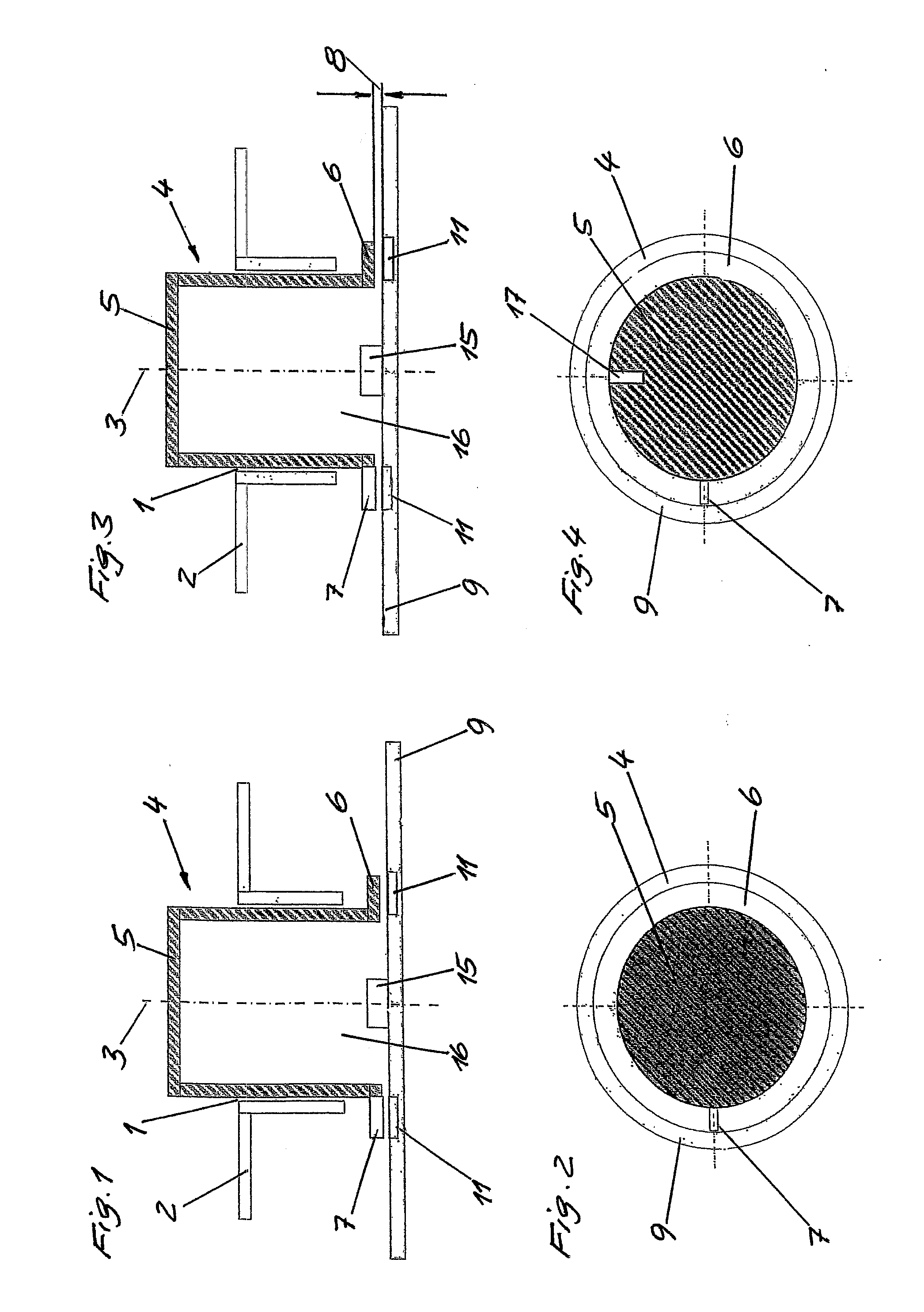
[0028]The rotary actuators of the exemplary embodiments have a pot-like handle 4 rotatable about an axis of rotation 3 in a recess 1 in a front panel 2.

[0029]On the operating side, the handle 4 closed by a base 5 projects from the front panel 2 and can be gripped and rotated by an operator.

[0030]At the end thereof opposite to the base 5, the handle 4 is formed with a ring-like collar 6 extending radially outward.

[0031]The handle 4 including collar 6 is an injection molded part.

[0032]Injection molded into the collar 6 at the same time is an actuating segment 7 made of conductive plastic.

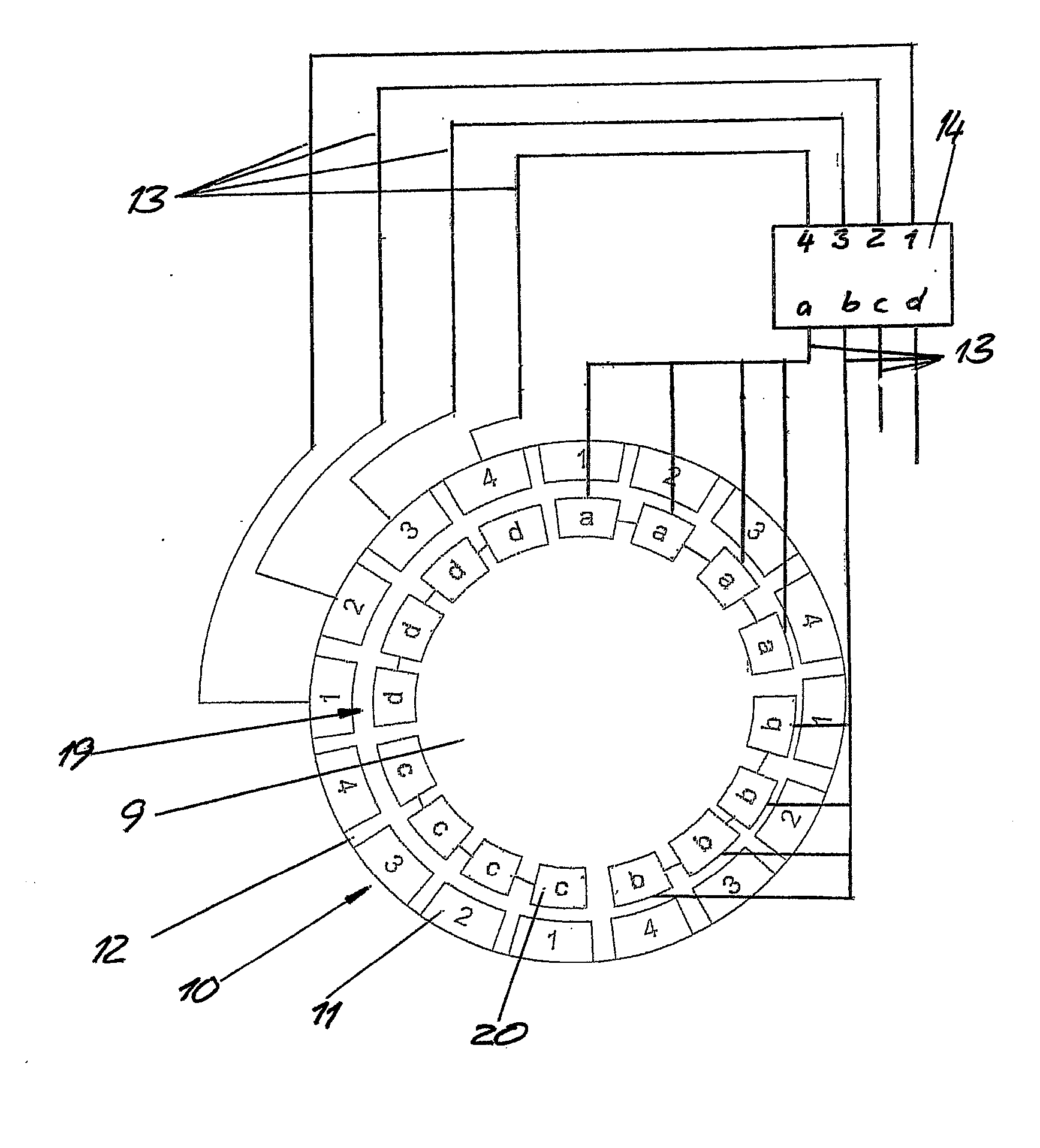
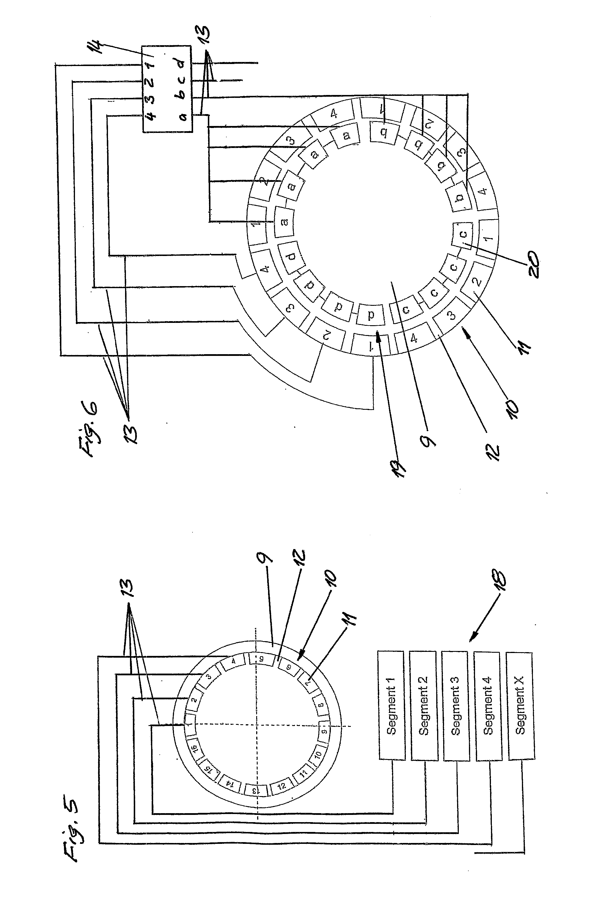
[0033]Arranged spaced apart from the collar 6 by an air gap forming a dielectric is a printed circuit board 9, which bears a segment ring 10 made of sensor segments 11 formed on the printed circuit board 9 as applied copper areas.

[0034]The sixteen sensor segments 11 are arranged distributed uniformly at distances 12 from one another on the circumference of the segment ring 10 that is concentric with r...


PUM


Abstract

A rotary actuator has a handle, rotatable about an axis of rotation, and a position sensor system for detecting the rotary position of the handle. The rotary actuator has an actuating segment is made of an electrically conductive material and, forming a capacitor, is opposite a sensor segment of a stationary segment ring, which is concentric with respect to the axis of rotation 3 and consists of a plurality of sensor segments. The sensor segments include an electrically conductive material and are axially spaced apart by an air gap. A sensor line leads from each sensor segment to evaluation electronics.

Description

PRIORITY CLAIM[0001]This is a U.S. national stage of PCT International Application No. PCT / EP2011 / 064513, filed on 24 Aug. 2011, which claims priority to German Application No. 10 2010 036 006.6, filed 31 Aug. 2010, the contents of which are incorporated herein by reference in its entirety.BACKGROUND OF THE INVENTION[0002]1. Field of the Invention[0003]The present invention relates to a rotary actuator having a handle which is rotatable about an axis of rotation, and a position sensor system for detecting the rotary position of the handle.[0004]2. Description of the Related Art[0005]In the case of such rotary actuators, it is known to carry out the detection of the rotary position of the handle with potentiometers, encoders, light barriers or Hall sensors.[0006]These rotary position detections are complicated and expensive.SUMMARY OF THE INVENTION[0007]It is therefore an object of the present invention to devise a rotary actuator which has a simple and inexpensive structure.[0008]Ac...

Claims


Application Information

Patent Timeline
IPC IPC(8): G01B7/30
CPCG01D5/2415G05G1/08G05G5/03H01H2239/006G01B7/30H03K2217/94073B60K37/06B60K2350/102H03K17/975B60K2370/126B60K2370/158
Inventor PFENNING, KLAUS
Owner CONTINENTAL AUTOMOTIVE GMBH
Why Eureka
Try Eureka