Display system in an excavator and method for controlling same

a technology of display system and excavating machine, which is applied in the direction of mechanical machines/dredgers, navigation instruments, instruments, etc., can solve the problems of difficult to ascertain the size of the display screen is too small, and the positional relationship between the target surface and the work machine is difficult to ascertain, so as to achieve and easy ascertaining the positional relationship relationship

Active Publication Date: 2013-06-20
KOMATSU LTD
View PDF12 Cites 28 Cited by
  • Summary
  • Abstract
  • Description
  • Claims
  • Application Information

AI Technical Summary

Benefits of technology

[0005]An object of the present invention is to provide a display system in an excavator and method for controlling the same allowing the positional relationship between an excavator and a display object surface displayed in a guidance picture to be easily ascertained.
[0010]In the display system in the excavator according to the first aspect of the present invention, the reference point of the display range of the guidance picture is fixed at the predetermined position between the upper boundary line and the lower boundary line when the current position of the excavator is between the upper boundary line and the lower boundary line. Thus, the excavator is displayed moving tip or down without the cross section of the display object surface moving in the guidance picture when the excavator moves up or down between the upper boundary line and the lower boundary line. When the excavator moves above the upper boundary line, the reference point of the display range is changed to a position above the predetermined position. The cross section of the display object surface thereby moves downward in the guidance picture, and the display range is displayed moving upward after the excavator. When the excavator moves below the lower boundary line, the reference point of the display range is changed to a position below the predetermined position. The cross section of the display object surface thereby moves upward in the guidance picture, and the display range is displayed moving downward after the excavator. This prevents the target surface and the excavator from being displayed excessively small. An operator can therefore easily ascertain the positional relationship of the target surface and the excavator.
[0011]In the display system in the excavator according to the second aspect of the present invention, the reference point of the display range is changed to a position above the predetermined position according to the distance by which the current position of the excavator is higher than the upper boundary line. The reference point of the display range is changed to a position below the predetermined position according to the distance by which the current position of the excavator is lower than the lower boundary line. This enables the guidance picture to be scrolled smoothly.
[0012]In the excavator according to the hi rd aspect of the present invention, the reference point of the display range of the guidance picture is fixed at the predetermined position between the upper boundary line and the lower boundary line when the current position of the excavator is between the upper boundary line and the lower boundary line. Thus, the excavator is displayed moving up or down without the cross section of the display object surface moving in the guidance picture when the excavator moves up or down between the upper boundary line and the lower boundary line. When the excavator proves above the upper boundary lure, the reference point of the display range is changed to a position above the predetermined position. The cross section of the display object surface thereby moves downward in the guidance picture, and the display range is displayed moving upward after the excavator. When the excavator moves below the lower boundary line, the reference point of the display range is changed to a position below the predetermined position. The cross section of the display object surface thereby moves upward in the guidance picture, and the display range is displayed moving downward after the excavator. This prevents the target surface and the excavator from being displayed excessively small. An operator can therefore easily ascertain the positional relationship of the target surface and the excavator.
[0013]In the method for controlling a display system in an excavator according to the fourth aspect of the present invention, the reference point of the display range of the guidance picture is fixed at the predetermined position between the upper boundary line and the lower boundary line when the current position of the excavator or is between the upper boundary line and the lower boundary line. Thus, the excavator is displayed moving up or down without the cross section of the display object surface moving in the guidance picture when the excavator moves up or down between the upper boundary line and the lower boundary line. When the excavator or moves above the upper boundary line, the reference point of the display range is changed to a position above the predetermined position. The cross section of the display object surface thereby moves downward in the guidance picture, and the display range is displayed moving upward after the excavator. When the excavator moves below the lower boundary line, the reference point of the display range is changed to a position below the predetermined position. The cross section of the display object surface thereby moves upward in the guidance picture, and the display range is displayed moving downward after the excavator. This prevents the target surface and the excavator from being displayed excessively small. An operator can therefore easily ascertain the positional relationship of the target surface and the excavator.

Problems solved by technology

When the display scale of the image is changed according to the distance between the target surface and the work machine, as in the display system disclosed in patent document 1, the target surface and the work machine can be displayed at an excessively small size, making it difficult to ascertain the positional relationship of the target surface and the work machine.
It is therefore difficult to ascertain the positional relationship between the target surface and the excavator.

Method used


Image

  • Display system in an excavator and method for controlling same
  • Display system in an excavator and method for controlling same
  • Display system in an excavator and method for controlling same

Examples


Embodiment Construction

1. Configuration

1-1. Overall Configuration of Hydraulic Shovel

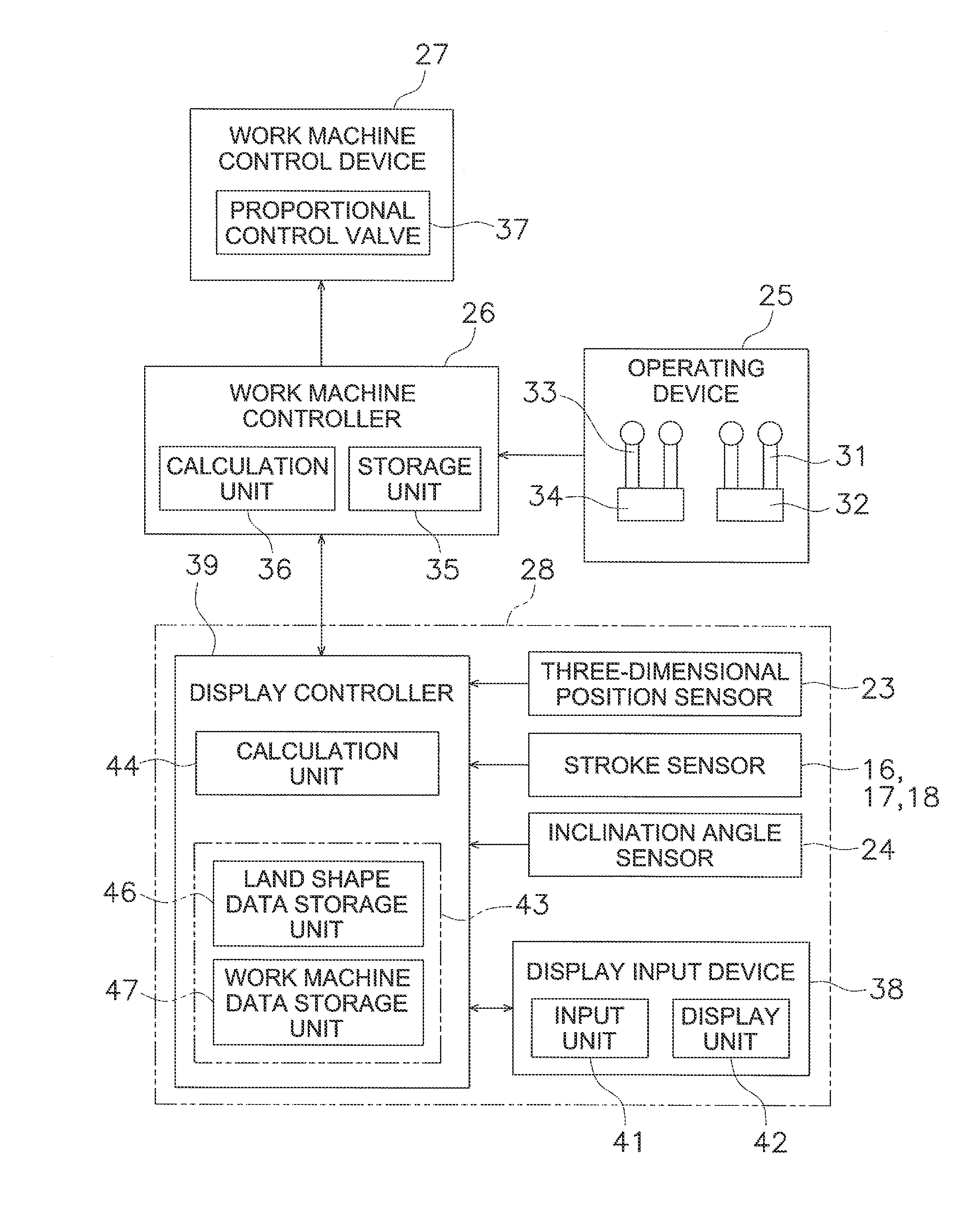
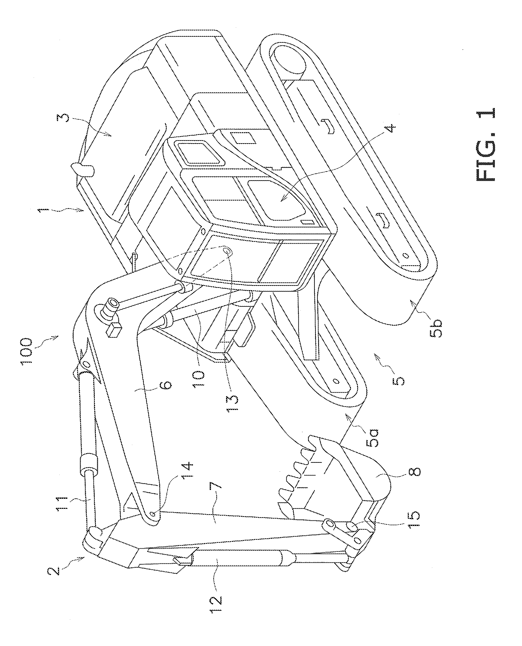
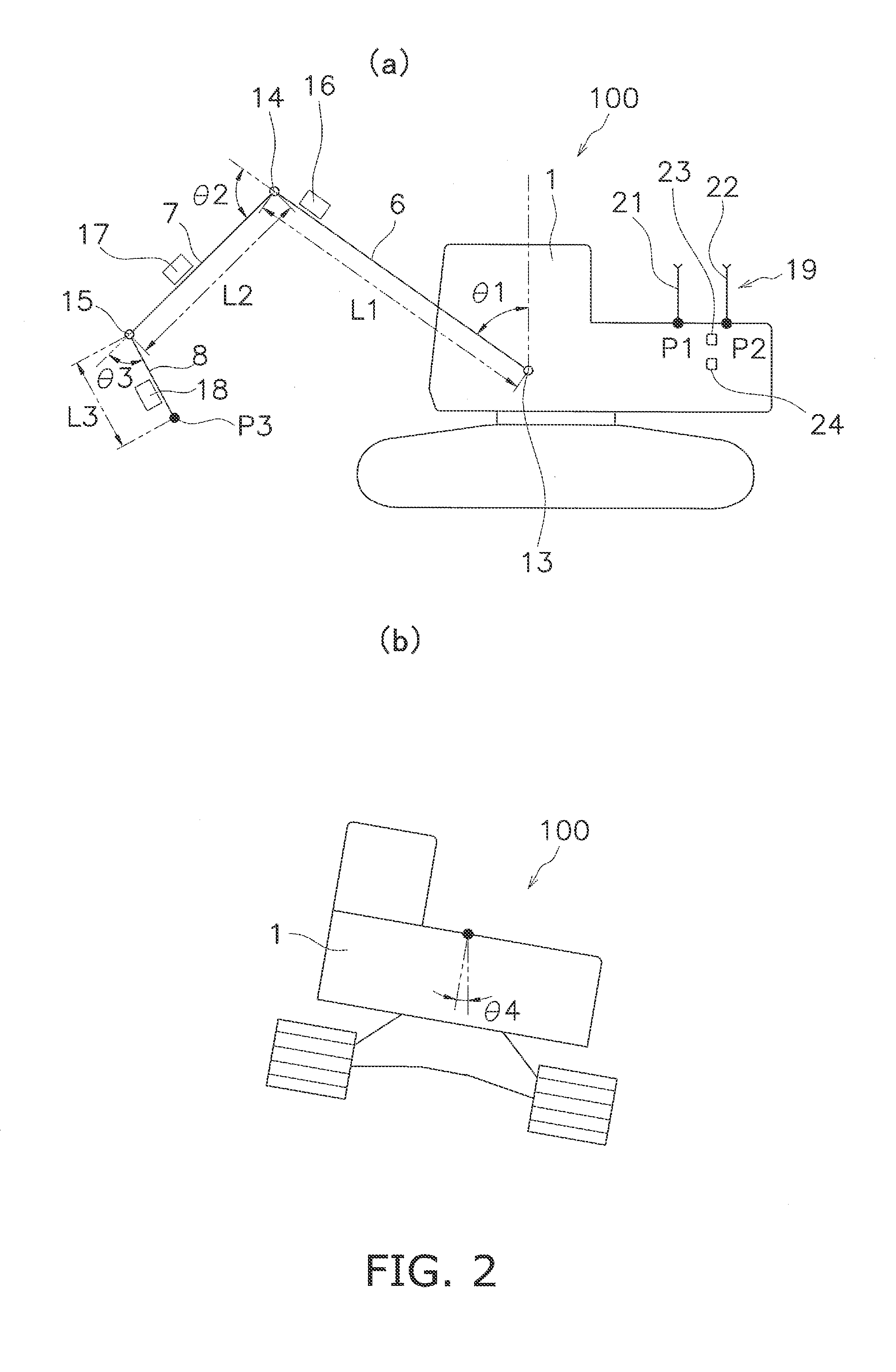
[0041]There follows a description of a display system in an excavator according to an embodiment of the present invention with reference to the drawings. FIG. 1 is a perspective view of a hydraulic shovel 100 as an example of an excavator in which a display system is installed. The hydraulic shovel 100 has a main vehicle body 1 and a work machine 2. The main vehicle body 1 has an upper pivoting body 3, a cab 4, and a travel unit 5. The upper pivoting body 3 includes devices such as an engine, a hydraulic pump, and / or the like, which are not shown in the drawings. The cab 4 is installed on the front of the upper pivoting body 3. A display input device 38 and an operating device 25 described below are disposed within the cab 4 (cf. FIG. 3). The travel unit 5 has tracks 5a, 5b, and the rotation of the tracks 5a, 5b causes the hydraulic shovel 100 to travel,

[0042]The work machine 2 is attached to the front of the main vehicle...


PUM


Abstract

In a display system in an excavator, a position of an upper boundary line and a position of a lower boundary line are calculated. The upper boundary line indicates a height of a top of a cross section of a display object surface. The lower boundary line indicates a height of a bottom of the cross section of the display object surface. When the current position of the excavator is between the upper boundary line and the lower boundary line, a predetermined reference point of a display range is set to a predetermined position between the upper and lower boundary lines. When the current position of the excavator is above the upper boundary line, the reference point is set above the predetermined position. When the current position of the excavator is below the lower boundary line, the reference point is set below the predetermined position.

Description

CROSS-REFERENCE TO RELATED APPLICATIONS[0001]This application claims priority to Japanese Patent Application No. 2011-036201 filed on Feb. 22, 2011, the disclosure of which is hereby incorporated herein by reference in its entirety.TECHNICAL FIELD[0002]The present invention relates to a display system in an excavator and a method for controlling same.BACKGROUND ART[0003]A display system for displaying a guidance picture displaying the positional relationship of a target surface and an excavator such as a hydraulic shovel is known. The target surface is a plane selected as a work object from a plurality of design surfaces constituting a design land shape. For example, in the display system disclosed in Japanese Laid-open Patent Application Publication 2001-123476, the relative positional relationship of a bucket and a target surface is calculated based on detection data such as the position and orientation of a bucket of a hydraulic shovel, and the position, gradient, and the like of...

Claims


Application Information

Patent Timeline
Patent Type & Authority Applications(United States)
IPC IPC(8): E02F9/26
CPCE02F9/264E02F9/26G01C21/00E02F3/43E02F9/2045E02F9/2054E02F9/2221E02F9/261G01C21/20E02F9/22
Inventor FUKANO, RYONOMURA, AZUMIKURIHARA, TAKASHIFUJITA, ETSUOANDO, MASAOKOIDE, TOSHIHIRO
Owner KOMATSU LTD
Why Eureka
Try Eureka