Wireless energy transfer modeling tool

a wireless energy transfer and modeling tool technology, applied in the field ofwireless energy transfer, can solve the problems of tripping hazards, unpractical wired connection, and difficulty in wireless energy transfer over a larger area, and achieve the effect of reducing the risk of tripping, and reducing the possibility of wire tangles

Active Publication Date: 2013-06-20
WITRICITY CORP
View PDF1 Cites 220 Cited by
  • Summary
  • Abstract
  • Description
  • Claims
  • Application Information

AI Technical Summary

Benefits of technology

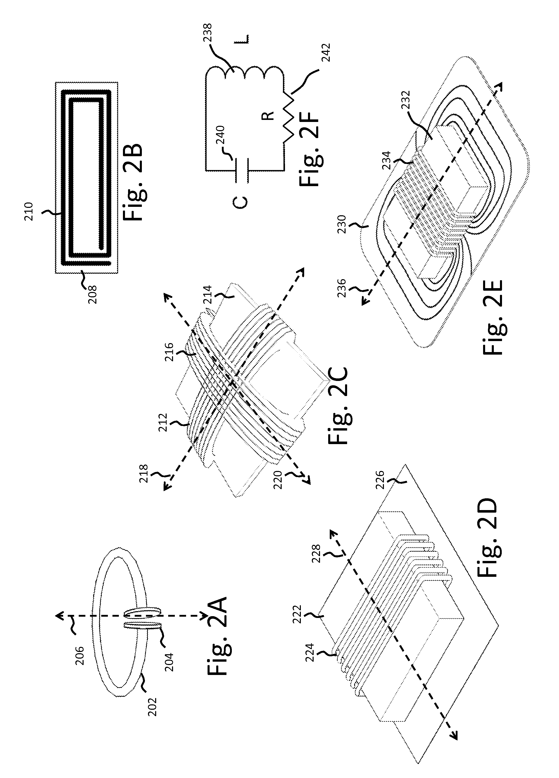
[0012]This disclosure references certain individual circuit components and elements such as capacitors, inductors, resistors, diodes, transformers, switches and the like; combinations of these elements as networks, topologies, circuits, and the like; and objects that have inherent characteristics such as “self-resonant” objects with capacitance or inductance distributed (or partially distributed, as opposed to solely lumped) throughout the entire object. It would be understood by one of ordinary skill in the art that adjusting and controlling variable components within a circuit or network may adjust the performance of that circuit or network and that those adjustments may be described generally as tuning, adjusting, matching, correcting, and the like. Other methods to tune or adjust the operating point of the wireless power transfer system may be used alone, or in addition to adjusting tunable components such as inductors and capacitors, or banks of inductors and capacitors. Those skilled in the art will recognize that a particular topology discussed in this disclosure can be implemented in a variety of other ways.
[0013]Unless otherwise defined, all technical and scientific terms used herein have the same meaning as commonly understood by one of ordinary skill in the art to which this disclosure belongs. In case of conflict with publications, patent applications, patents, and other references mentioned or incorporated herein by reference, the present specification, including definitions, will control.

Problems solved by technology

Energy distribution over an area to moving devices or devices that may be often repositioned is unpractical with wired connections.
Moving and changing devices create the possibility of wire tangles, tripping hazards, and the like.
Wireless energy transfer over a larger area may be difficult when the area or region in which devices may be present may be large compared to the size of the device.
Large mismatches in a source and device wireless energy capture modules may pose challenges in delivering enough energy to the devices at a high enough efficiency to make the implementations practical or may be difficult to deploy.

Method used


Image

  • Wireless energy transfer modeling tool
  • Wireless energy transfer modeling tool
  • Wireless energy transfer modeling tool

Examples


Embodiment Construction

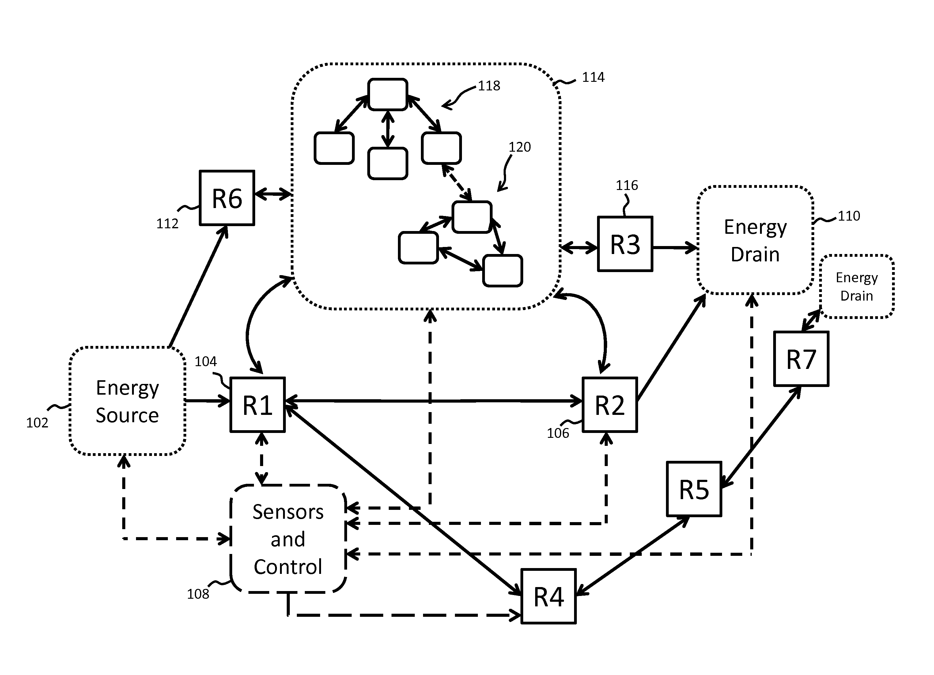
[0080]As described above, this disclosure relates to wireless energy transfer using coupled electromagnetic resonators. However, such energy transfer is not restricted to electromagnetic resonators, and the wireless energy transfer systems described herein are more general and may be implemented using a wide variety of resonators and resonant objects.

[0081]As those skilled in the art will recognize, important considerations for resonator-based power transfer include resonator efficiency and resonator coupling. Extensive discussion of such issues, e.g., coupled mode theory (CMT), coupling coefficients and factors, quality factors (also referred to as Q-factors), and impedance matching is provided, for example, in U.S. patent application Ser. No. 12 / 789,611 published on Sep. 23, 2010 as US 20100237709 and entitled “RESONATOR ARRAYS FOR WIRELESS ENERGY TRANSFER,” and U.S. patent application Ser. No. 12 / 722,050 published on Jul. 22, 2010 as US 20100181843 and entitled “WIRELESS ENERGY T...


PUM


Abstract

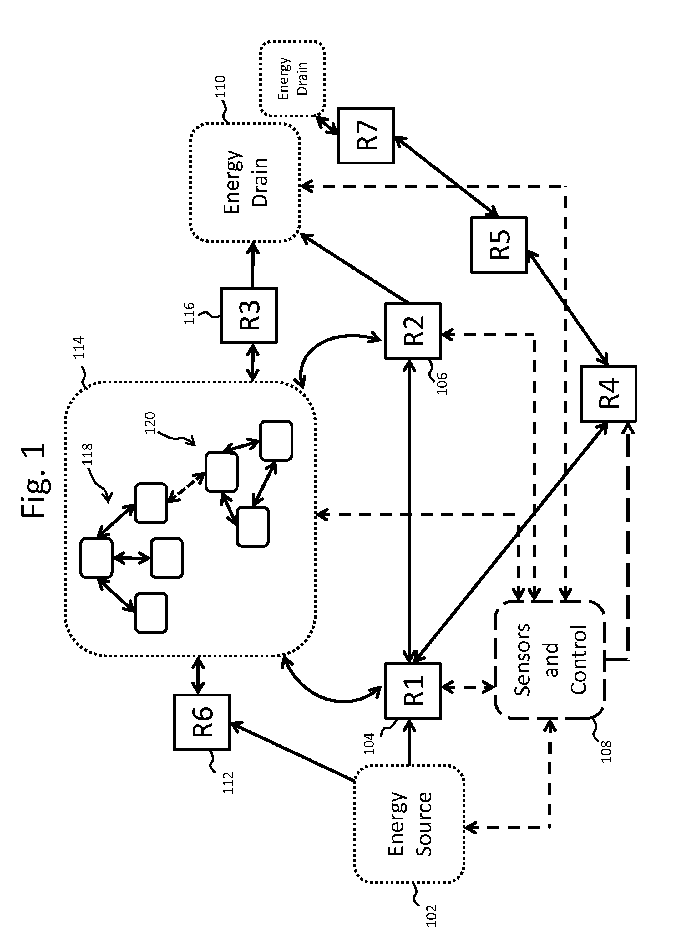
A method includes defining and storing one or more attributes of a source resonator and a device resonator forming a system, defining and storing the interaction between the source resonator and the device resonator, modeling the electromagnetic performance of the system to derive one or more modeled values and utilizing the derived one or more modeled values to design an impedance matching network.

Description

CROSS-REFERENCE TO RELATED APPLICATIONS[0001]This application claims the benefit of U.S. provisional patent application 61 / 555,941 filed Nov. 4, 2011.[0002]Each of the foregoing applications is incorporated herein by reference in its entirety.BACKGROUND[0003]1. Field[0004]This disclosure relates to wireless energy transfer, methods, systems and apparati to accomplish such transfer, and applications.[0005]2. Description of the Related Art[0006]Energy distribution over an area to moving devices or devices that may be often repositioned is unpractical with wired connections. Moving and changing devices create the possibility of wire tangles, tripping hazards, and the like. Wireless energy transfer over a larger area may be difficult when the area or region in which devices may be present may be large compared to the size of the device. Large mismatches in a source and device wireless energy capture modules may pose challenges in delivering enough energy to the devices at a high enough ...

Claims


Application Information

Patent Timeline
Patent Type & Authority Applications(United States)
IPC IPC(8): G06F17/50
CPCG06F17/5009G06F17/50G06F2217/78G06F17/5036G06F30/367G06F2119/06G06F30/20H02J50/12G06F30/00
Inventor VERGHESE, SIMONEFE, VOLKANKESLER, MORRIS P.KURS, ANDRE B.KARALIS, ARISTEIDISMCCAULEY, ALEXANDER PATRICKHIJARRUBIA, MARIA EMPAR ROLLANO
Owner WITRICITY CORP
Why Eureka
Try Eureka