Mobile communication terminal

a mobile communication and terminal technology, applied in the field of mobile communication terminals, can solve the problems of channel status, low accuracy of receiving weights calculated, and low accuracy of receiving weights, etc., and achieve the effect of small merit, good reception quality and good reception quality

Inactive Publication Date: 2013-06-27
NTT DOCOMO INC
View PDF2 Cites 10 Cited by
  • Summary
  • Abstract
  • Description
  • Claims
  • Application Information

AI Technical Summary

Benefits of technology

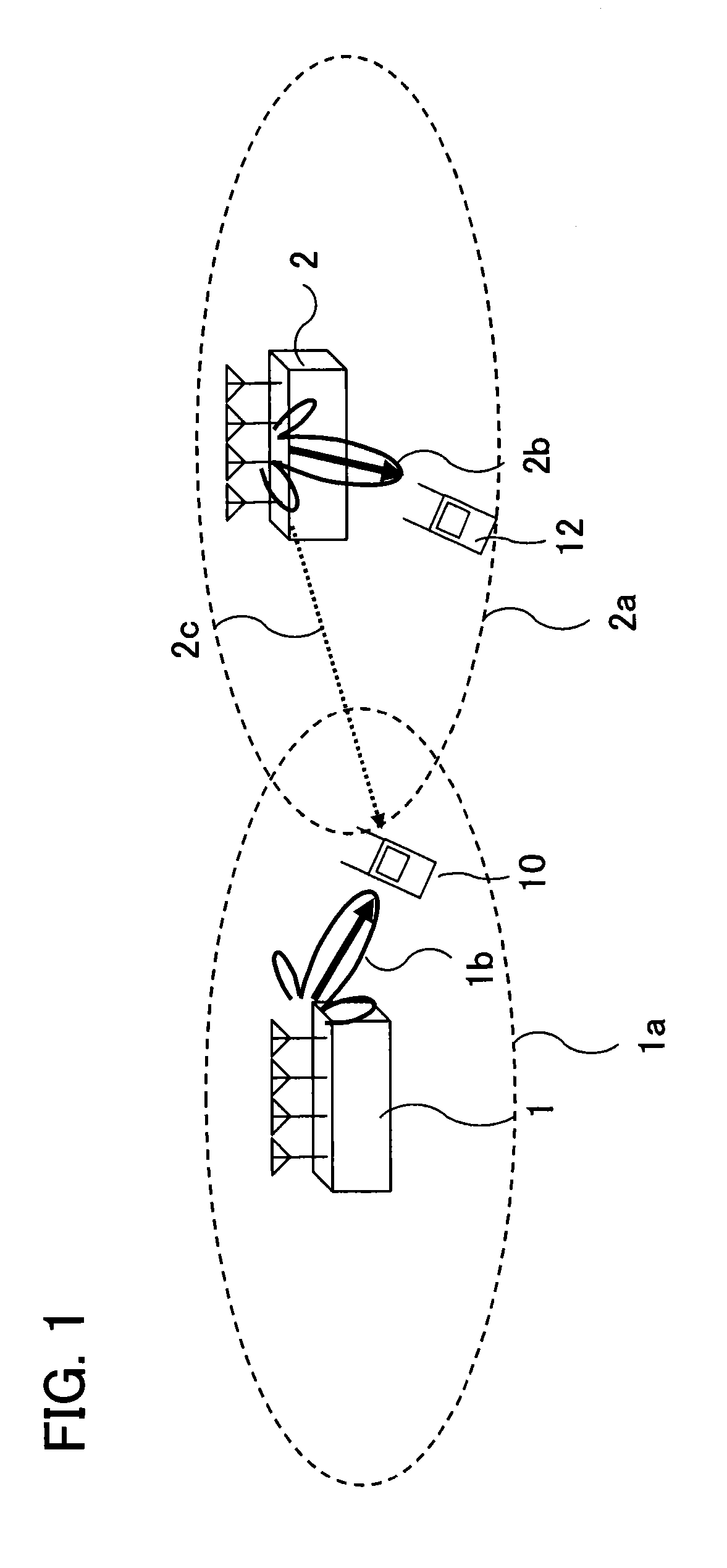
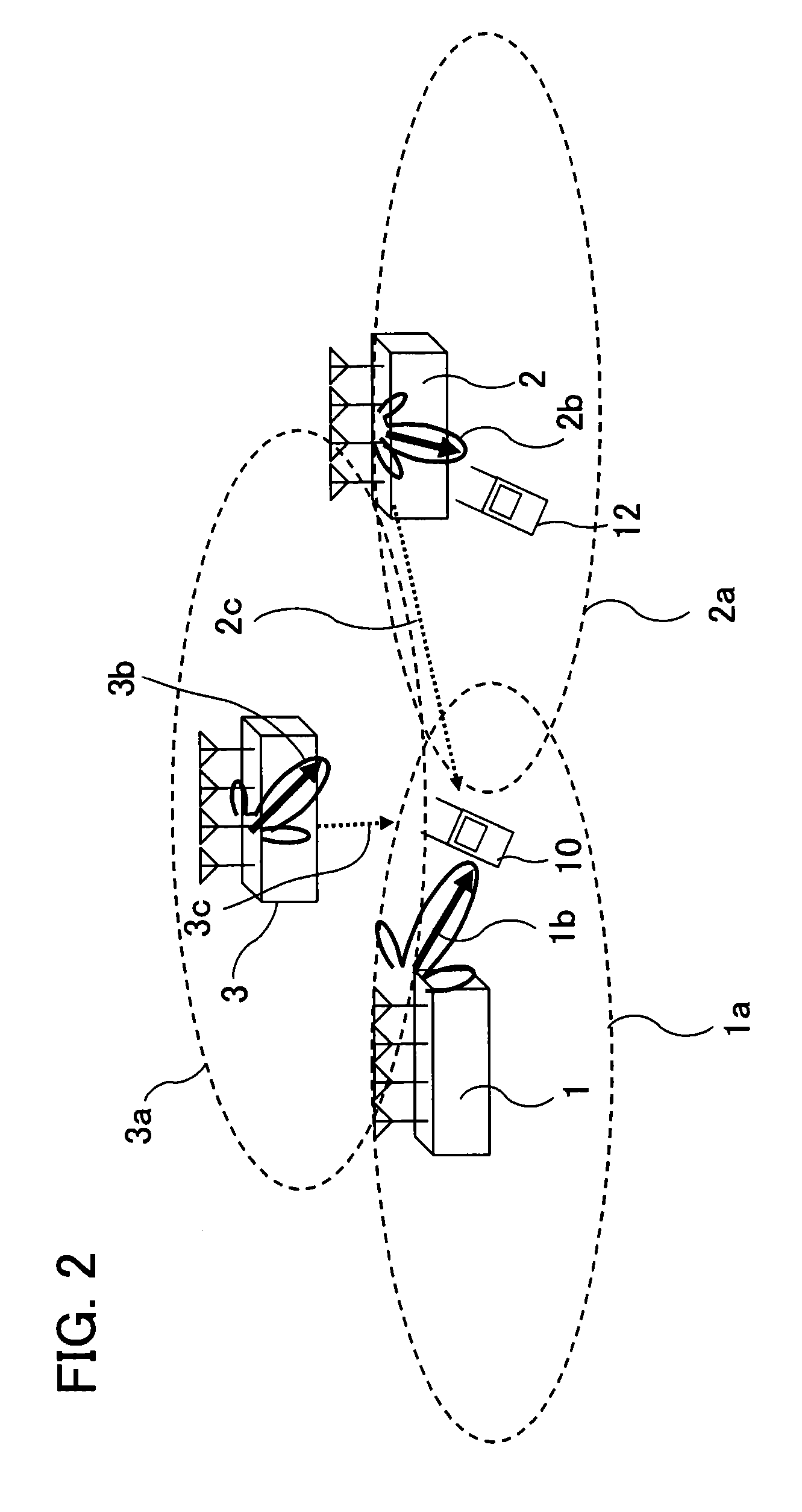
[0034]With such a structure, the first demodulator demodulates the signal destined for the mobile communication terminal that was subjected to interference rejection combining, and the first error decider decides existence or non-existence of errors in the signal demodulated by the first demodulator. On the other hand, the second demodulator demodulates the signal destined for the mobile communication terminal that was not subjected to interference rejection combining, and the second error decider decides existence or non-existence of errors in the signal demodulated by the second demodulator. On the basis of error decision by the first error decider and error decision by the second error decider, the interference rejection combining determiner determines whether the signal demodulated by the first demodulator or the signal demodulated by the second demodulator should be output. A mobile communication terminal located at the center of a cell is less affected by interfering signals, so that interference r...

Problems solved by technology

In the above-described IRC reception method for calculating receiving weights with the use of Equation (2), accuracy of receiving weights calculated actually may be frequently low, and as a result, even if the mobile communication terminal separates the signal destined for the mobile communication terminal, the quality of the signal may be frequently low.
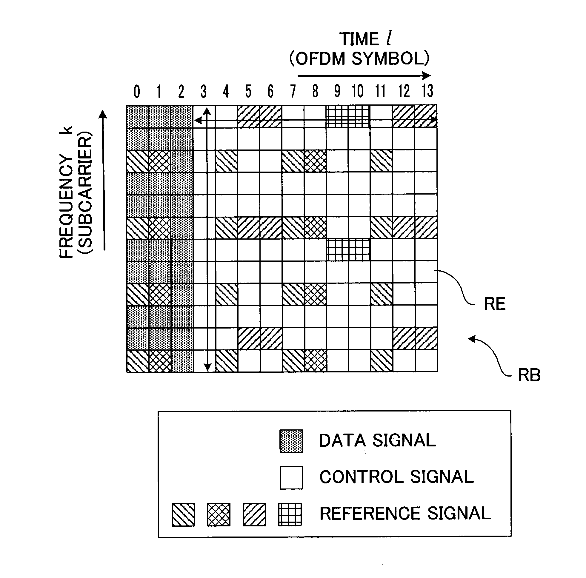
On the other hand, in the sampling technique for the entire resource block described above with reference to FIG. 4, the calculated covariance matrix of received signal vectors may al...

Method used


Image

  • Mobile communication terminal
  • Mobile communication terminal
  • Mobile communication terminal

Examples


first embodiment

[0050]FIG. 5 is a block diagram showing the structure of the mobile communication terminal according to the first embodiment of the present invention. FIG. 5 shows only parts involved in signal reception and does not show other parts. As shown in FIG. 5, each mobile communication terminal includes multiple receiving antennas 20 for receiving electric wave, and a radio receiver 22 that is a reception circuit applied to OFDMA for converting electric wave received at the receiving antennas 20 to an electric signal.

[0051]Furthermore, the mobile communication terminal includes a control signal recognizer 24, a UE-specific reference signal demodulator 26, an interference rejection combining processor 32, a non-interference-rejection receiving weight calculator 33, a signal separator 34, a demodulator 36, a cell search executor 38, a quality ratio calculator 41, an interference rejection combining determiner 42, a control signal recognizer 24, and a threshold setter 46. These structural el...

second embodiment

[0074]The structure of a mobile communication terminal according to a second embodiment of present invention is the same as that of the first embodiment that has been described with reference to FIG. 5. In the following, characteristics of the second embodiment that differ from the first embodiment will be described in detail.

[0075]At the cell search, the reception quality measurer 40 measures reception qualities of at least three synchronization signals sent from different base stations and received by the mobile communication terminal. The quality ratio calculator 41 calculates a ratio of the reception quality of the signal from the desired base station (that is decided at the cell search) measured by the reception quality measurer 40 to a reception quality of another signal from each of at least two base stations measured by the reception quality measurer 40. In other words, the quality ratio calculator 41 calculates multiple the quality ratio RQ in accordance with the equation b...

third embodiment

[0083]FIG. 8 is a block diagram showing the structure of a mobile communication terminal according to a third embodiment of the present invention. FIG. 8 shows only parts involved in signal reception and does not show other parts. In FIG. 8, the same reference symbols are used to identify elements commonly used in the first embodiment in FIG. 5, and these elements will not be described in detail.

[0084]The mobile communication terminal according to the third embodiment includes a channel quality indicator (CQI) calculator 50 for calculating a channel quality indicator on the basis of the power of the signal received from the desired base station and the power of the interfering signal. The CQI may be any one of the SNR (signal-to-noise ratio), the SIR (signal-to-interference ratio), the SINR (signal-to-interference-plus-noise ratio), and the SDNR (signal-to-distortion-plus-noise ratio).

[0085]The interference rejection combining determiner 42 compares the CQI calculated by the CQI cal...


PUM


Abstract

A mobile communication terminal includes an interference rejection combining processor for obtaining a received signal vector with regard to each of multiple resource elements and for calculating receiving weights so as to suppress influence to a desired beam of electric wave sent from the desired base station by other beams, on the basis of the received signal vectors; a non-interference-rejection receiving weight calculator for calculating receiving weights so as not to suppress influence to the desired beam by other beams; a signal separator for separating a signal destined for the mobile communication terminal from signals destined for other mobile communication terminals; and an interference rejection combining determiner for determining whether the receiving weights to suppress influence by other beams or the receiving weights calculated by the non-interference-rejection receiving weight calculator should be used for signal separation by the signal separator, on the basis of an index representing a relationship between reception quality of a desired downlink transmission signal and reception quality of an interfering signal.

Description

FIELD OF THE INVENTION[0001]The present invention relates to a mobile communication terminal.BACKGROUND ART[0002]In LTE (Long Term Evolution) Advanced of 3GPP (Third Generation Partnership Project), OFDMA (Orthogonal Frequency Division Multiplexing Access) using MU-MIMO (multi-user multiple-input multiple-output) has been proposed. In MU-MIMO downlink transmission, a base station is able to not only communicate with multiple mobile communication terminals, but also to transmit different data streams (layers) simultaneously to a mobile communication terminal.[0003]In addition, in LTE Advanced, a reception technique for mobile communication terminals called as interference rejection combining has been discussed. Interference rejection combining (IRC) is a technique for downlink communication, in which a mobile communication terminal gives weights to signals obtained by reception antennas so as to suppress interference to the desired electric wave beam from the visited base station (de...

Claims


Application Information

Patent Timeline
IPC IPC(8): H04W24/02
CPCH04B7/0865H04L5/0023H04W24/02H04L5/0051H04L25/03891H04B7/0871H04L1/0009H04L1/0026H04L1/0036H04B7/0851H04B7/0857H04L1/0003
Inventor OHWATARI, YUSUKEMIKI, NOBUHIKOASAI, TAKAHIROOKUMURA, YUKIHIKO
Owner NTT DOCOMO INC
Why Eureka
Try Eureka