Variable displacement pump

a variable displacement, pump technology, applied in the direction of liquid fuel engines, machines/engines, rotary piston liquid engines, etc., can solve the problems of waste of energy, and possibility of large deviation of discharge pressure characteristics from required discharge pressure characteristics, so as to suppress excessive rise in discharge pressure

Active Publication Date: 2013-06-27
HITACHI ASTEMO LTD
View PDF5 Cites 34 Cited by
  • Summary
  • Abstract
  • Description
  • Claims
  • Application Information

AI Technical Summary

Benefits of technology

[0007]It is an object of the present invention to provide a variable displacement pump which can suppress an excessive rise in the discharge pressure even if the pump revolution speed is raised when a request to maintain the discharge pressure at a desired discharge pressure occurs.

Problems solved by technology

Then, a discharge pressure is raised excessively largely as a pump revolution speed is raised, even if the discharge pressure is maintained at the first discharge pressure or at the second discharge pressure, and there is a possibility of a large deviation of the discharge pressure characteristic from a required discharge pressure characteristic.
For example, the excessively large discharge quantity at a time of a high revolution speed of the pump is brought out and a wasteful consumption of energy is resulted.

Method used


Image

  • Variable displacement pump
  • Variable displacement pump
  • Variable displacement pump

Examples


first preferred embodiment

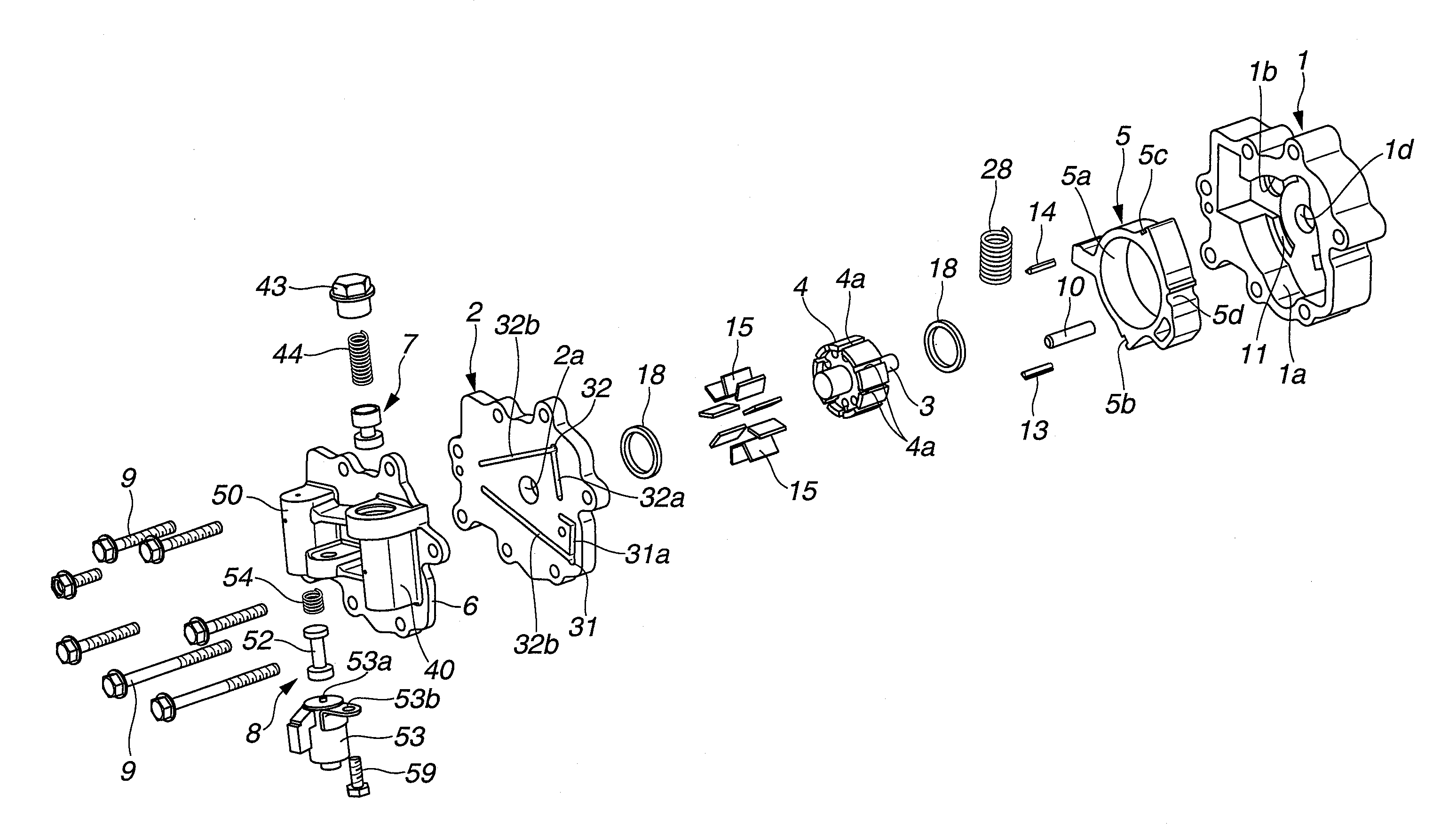
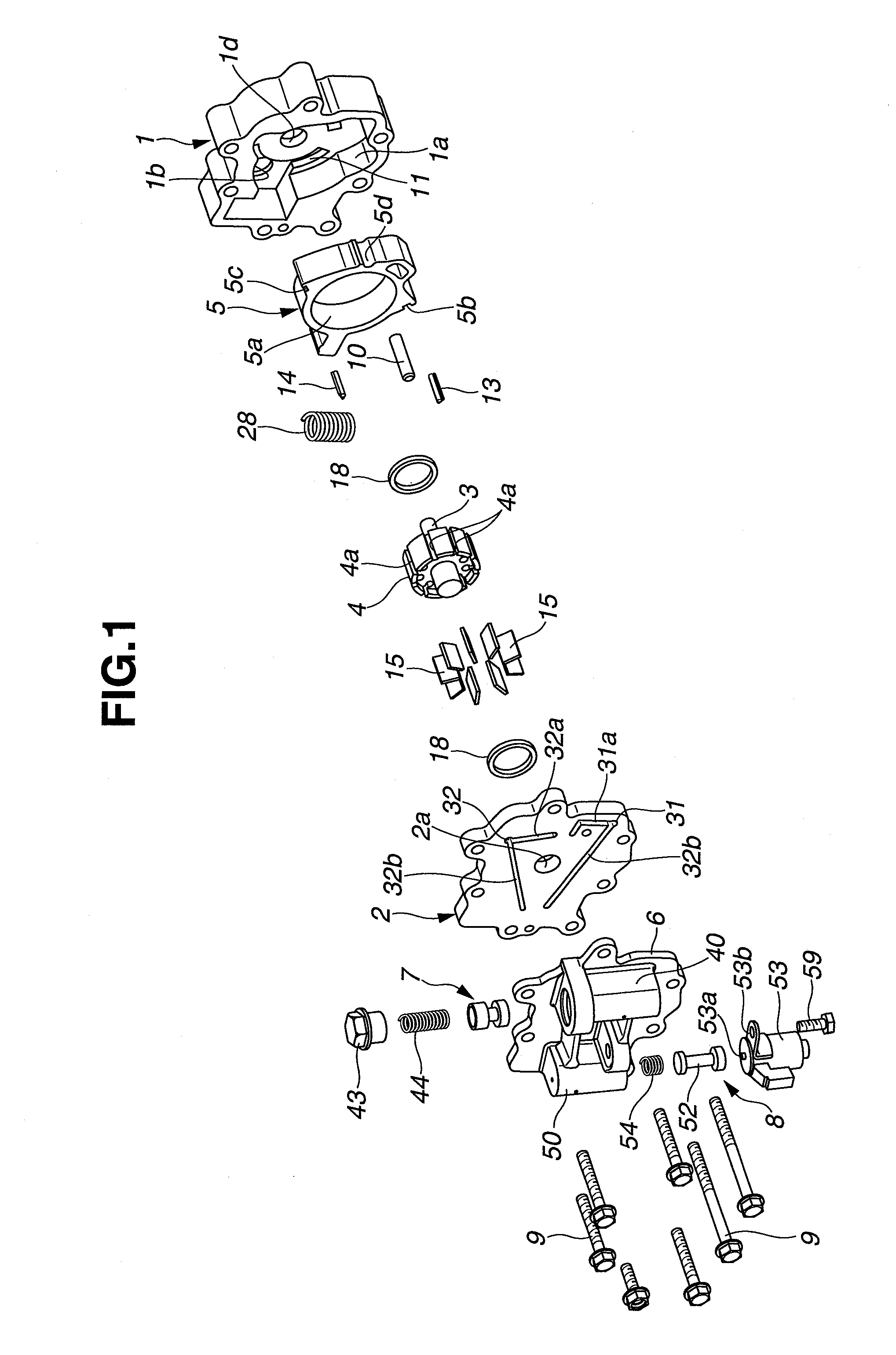
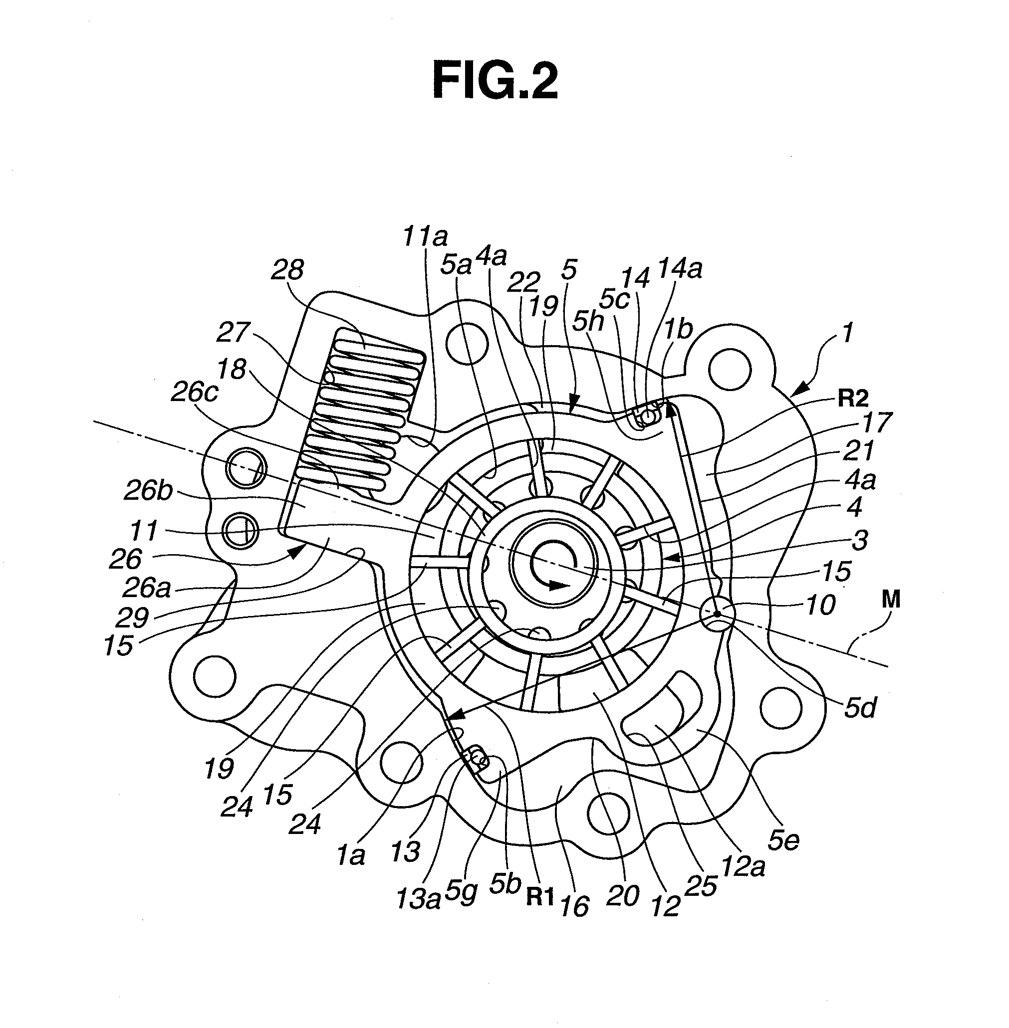
[0030]The variable displacement pump in a first preferred embodiment is applicable to a vane type variable displacement pump. The variable displacement pump is mounted at a front end section of a cylinder block of the internal combustion engine. As shown in FIGS. 1 and 2, the variable displacement pump mainly includes: a pump housing 1 of a bottomed cylindrical shape, pump housing 1 having one end opening closed with a pump cover 2; a driving shaft 3 penetrated through a substantial center section of pump housing 1 and rotationally driven through an engine crankshaft of the engine not shown; a rotor 4 rotatably housed within an inner part of pump housing 1, rotor 4 having a center section coupled to driving shaft 3; a cam ring 5 which is a movable member, cam ring 5 being swingably arranged onto an outer peripheral side of rotor 4; a control housing 6 fixedly arranged on an outside surface of pump cover 2; a pilot valve 7 which is a control mechanism to control a switching of a hydr...

second preferred embodiment

[0117]FIG. 13 shows a second preferred embodiment according to the present invention. A basic structure of the pump main body of the variable displacement pump in this embodiment is substantially the same as the structure of the first embodiment. In view of FIG. 13, the variable displacement pump is arranged in an inverted configuration. In addition, pilot valve 7 is integrally installed at pump cover 2 side but electromagnetic switching valve 8 is integrally installed at pump housing 1. The same reference numerals in the second embodiment as those in the first embodiment designate like elements in the second embodiment.

[0118]That is to say, pilot valve 7, as shown in FIG. 13, mainly includes: cylindrical first valve body 40; first spool valve 42 slidably mounted within first valve hole 41; and first valve spring 44 elastically interposed between plug 43 and first spool valve 42.

[0119]First spool valve 42 includes: first valve body 42a installed at the forward end side of first spoo...

third preferred embodiment

[0136]FIGS. 16, 17, and 18 show a third preferred embodiment of the variable displacement pump. In addition to pilot valve 7 and electromagnetic switching valve 8 described in the first embodiment, a second pilot valve 70 which is a second control mechanism is installed.

[0137]First, a modifying point on the structure of first pilot valve 7 will be described below. This first pilot valve 7 disuses second pilot control port 47 and the spring load of first valve spring 44 is set to correspond to a relatively low predetermined hydraulic pressure acted upon first hydraulic pressure introducing port 46 under which first valve spring 44 is compressively deformed to move first spool valve 42 in the backward direction.

[0138]Second pilot valve 70 has the substantially same structure as first pilot valve 7. Second pilot valve 70 includes: a third valve body 71 in the lidded cylindrical shape having the bottom section closed and installed in the vertical direction in parallel to first pilot val...


PUM


Abstract

A variable displacement pump includes: a first control oil chamber which moves a cam ring toward a direction against a biasing force of a biasing member when a discharge pressure is introduced thereinto; a second control oil chamber which acts a hydraulic pressure upon the cam ring by cooperating with the biasing force of the biasing member when hydraulic oil is introduced thereinto; a switching mechanism which switches between one state in which hydraulic oil whose pressure is decreased than a discharge pressure is introduced to the second control oil chamber from the discharge section and another state in which hydraulic oil is discharged from the second control oil chamber; and a control mechanism operated before an eccentricity of the cam ring becomes a minimum and which discharges a greater amount of hydraulic oil within the second control oil chamber as the discharge pressure becomes larger.

Description

BACKGROUND OF THE INVENTION[0001](1) Field of the Invention[0002]The present invention relates to a variable displacement pump for, for example, an internal combustion engine of an automotive vehicle.[0003](2) Description of related art[0004]Recently, there is an industrial demand for the variable displacement pump to have a two-stage characteristic such that a required discharge pressure is maintained at a first discharge pressure in a first pump revolution speed region and the required discharge pressure is maintained at a second discharge pressure in a second pump revolution region in order to use oil discharged from the oil pump to an equipment having different required discharge pressures such as each sliding portion of the engine and a variably operated valve apparatus which controls a working characteristic of an engine valve.[0005]In order to satisfy the above-described industrial demand, a Japanese Patent Application First Publication (tokuyou) No. 2008-524500 published on ...

Claims


Application Information

Patent Timeline
Patent Type & Authority Applications(United States)
IPC IPC(8): F04C2/00
CPCF04C14/226F04C2/344F04C2/348
Inventor OHNISHI, HIDEAKISAGA, KOJIWATANABE, YASUSHI
Owner HITACHI ASTEMO LTD
Why Eureka
Try Eureka