Power storage device

a power storage device and active material layer technology, applied in the field of power storage devices, can solve the problems of heat generation in the power storage device, deterioration of the negative electrode, and decreased uniformity of the electrode reaction, so as to reduce the amount of carrier ions, increase the resistance of the active material layer of the negative electrode, and increase the voltage of the power storage device

Inactive Publication Date: 2013-06-27
SEMICON ENERGY LAB CO LTD
View PDF7 Cites 30 Cited by
  • Summary
  • Abstract
  • Description
  • Claims
  • Application Information

AI Technical Summary

Benefits of technology

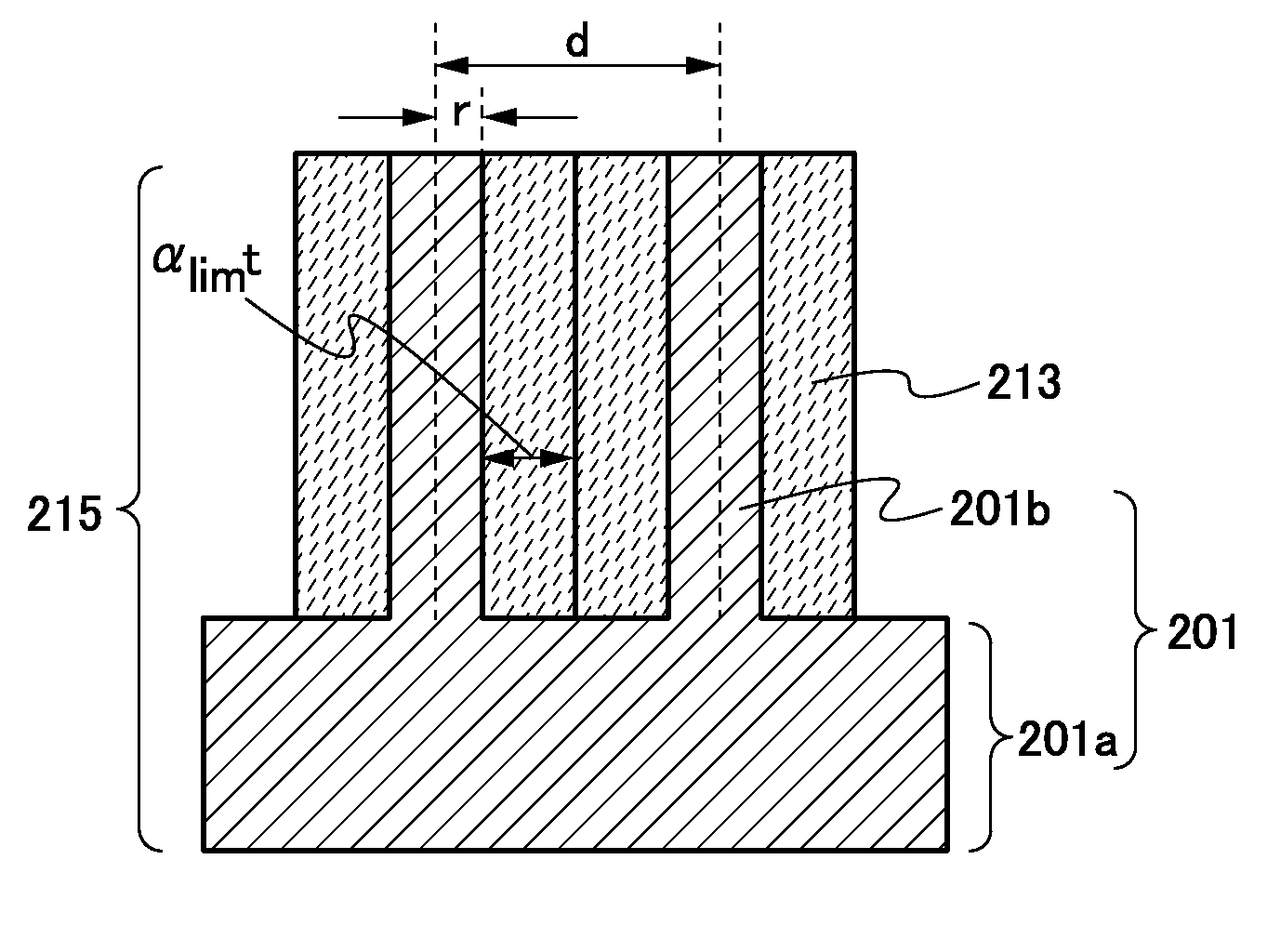
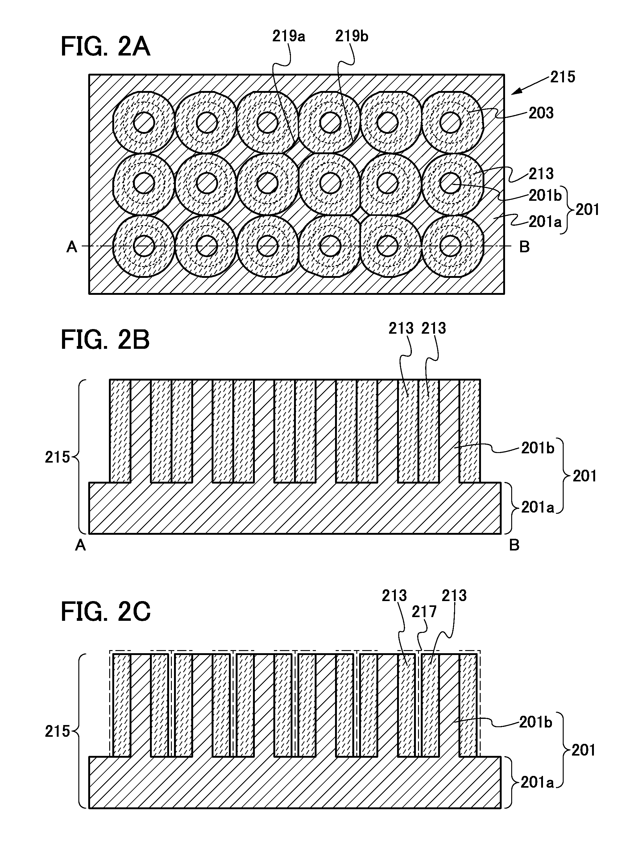
[0021]The amount of carrier ions to be inserted into the negative electrode active material layer is limited so that the amount of carrier ions inserted into the negative electrode active material layer does not reach the theoretical capacity of the negative electrode active material layer, whereby the expansion of the negative electrode active material layer can be limited. Thus, even if adjacent negative electrode active material layers are in contact with each other, distortion of the negative electrode active material layer is small, so that breakdown of the negative electrode active material layer can be prevented. Further, in the case where adjacent negative electrode active material layers are in contact with each other, the area of the negative electrode active material layer which is exposed to the electrolyte is decreased, resulting in a decrease in the amount of carrier ions to be inserted into the negative electrode active material layer; thus, the resistance of the negative electrode active material layer is increased. At this time, a voltage of the power storage device is increased owing to the increase in the resistance. Charge of the power storage device can be stopped by determining a change in the voltage with the use of an external circuit. That is, one embodiment of the present invention includes the negative electrode current collector including the protrusions, and the distance between adjacent protrusions is controlled so that adjacent negative electrode active material layers are in contact with each other when the capacity thereof reaches a predetermined capacity to control the amount of carrier ions to be inserted into the negative electrode active mat

Problems solved by technology

Thus, the uniformity of an electrode reaction is decreased and an excessive increase in volume and breakdown due to the excessive increase in volume occur in a region into which a larger amount of carrier ions is inserted, which causes deterioration of the negative electrode.
This might cause heat generation in the power storage dev

Method used


Image

  • Power storage device
  • Power storage device
  • Power storage device

Examples


embodiment 1

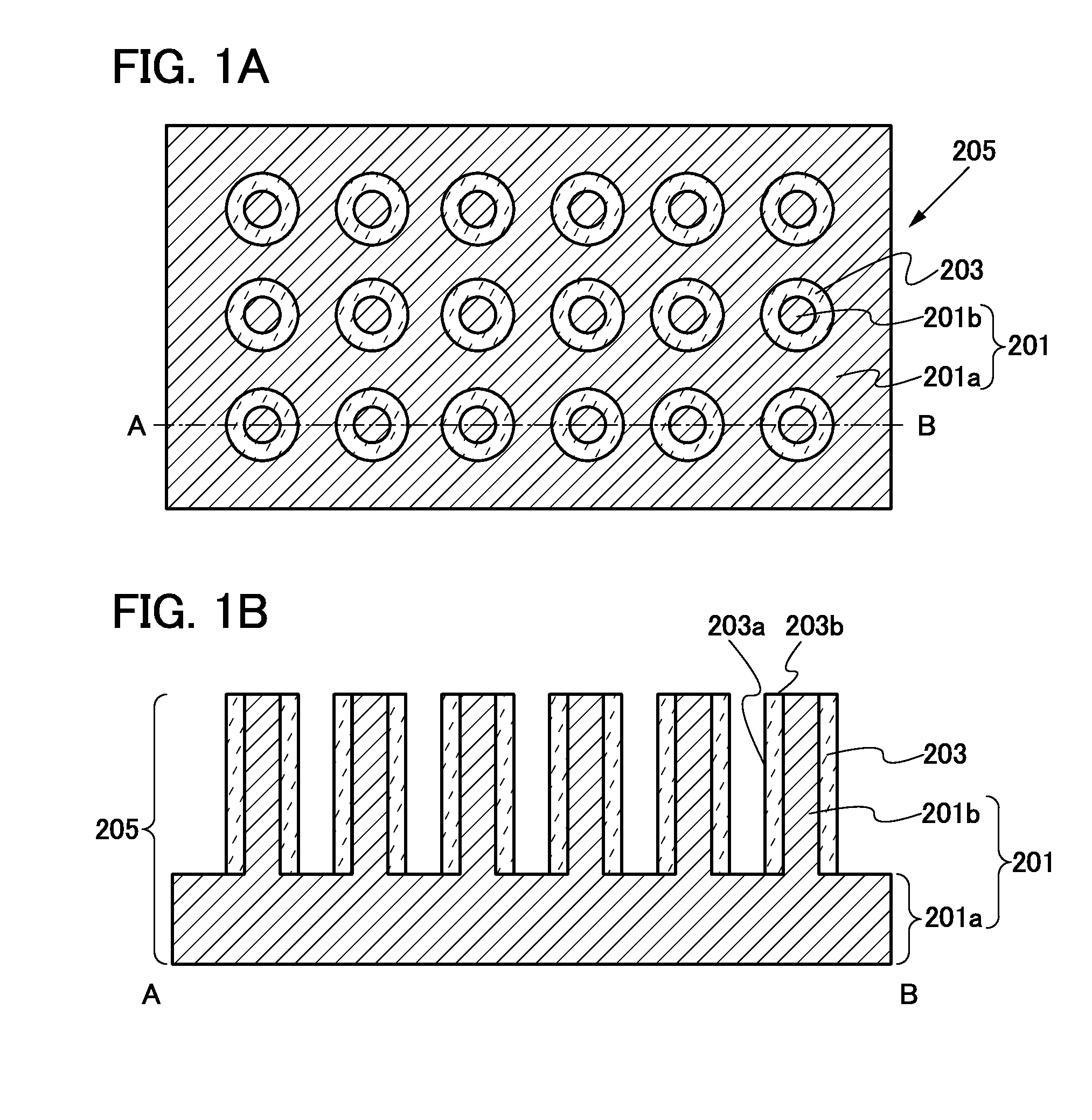
[0035]In this embodiment, the structure of a negative electrode in which deterioration of battery characteristics due to charge-discharge is small and a formation method thereof will be described with reference to FIGS. 1A and 1B, FIGS. 2A to 2C, FIGS. 3A and 3B, FIG. 4, and FIGS. 5A and 5B.

[0036]First, the structure of a power storage device will be described. Here, one embodiment of a lithium secondary battery which is a typical example of a power storage device in this embodiment will be described with reference to FIGS. 5A and 5B.

[0037]FIG. 5A is a perspective view of a coin-type lithium secondary battery 400. In the lithium secondary battery 400, an external terminal 417 and an external terminal 419 are provided with a gasket (not illustrated) provided therebetween.

[0038]FIG. 5B is a cross-sectional view of the coin-type lithium secondary battery 400 in a direction perpendicular to the top surface of the external terminal 417.

[0039]The lithium secondary battery 400 includes a p...

embodiment 2

[0100]In this embodiment, the structure of a negative electrode which can be used for the power storage device described in Embodiment 1 and a formation method thereof will be described with reference to FIGS. 7A and 7B and FIGS. 8A to 8D. The negative electrode described in this embodiment includes protective layers over the tops of the plurality of protrusions.

[0101]FIG. 7A is a top view of a negative electrode 235 described in this embodiment and FIG. 7B is a cross-sectional view taken along dashed-dotted line C-D in FIG. 7A.

[0102]The negative electrode 235 includes the negative electrode current collector 201 having the common portion 201a and the plurality of protrusions 201b protruding from the common portion 201a, protective layers 237 formed over the tops of the plurality of protrusions 201b, and a negative electrode active material layer 233 formed on side surfaces of the plurality of protrusions 201b and the protective layer 237. Further, the plurality of protrusions 201b ...

embodiment 3

[0116]In this embodiment, a mode in which graphene is provided over the negative electrode active material layer of the negative electrode described in Embodiment 1 will be described with reference to FIG. 9. Note that although description is made using Embodiment 1 in this embodiment, Embodiment 2 can also be used.

[0117]Graphene refers to a sheet of one atomic layer of carbon molecules having double bonds. Graphene is chemically stable and has favorable electric characteristics.

[0118]FIG. 9 illustrates an example in which graphene 247 is applied to the negative electrode described in Embodiment 1. The graphene 247 is formed so as to cover the surface of the common portion 201a of the negative electrode current collector 201, the top of the protrusion 201b of the negative electrode current collector 201, and the negative electrode active material layer 203. The graphene 247 may entirely or partially cover the surface of the common portion 201a of the negative electrode current colle...


PUM


Abstract

Disclosed is a power storage device including a negative electrode and a positive electrode. The negative electrode includes a negative electrode current collector including a common portion and a plurality of protrusions protruding from the common portion, and a negative electrode active material layer which covers a side surface of the protrusion. The positive electrode faces the negative electrode with an electrolyte provided therebetween. In the plurality of protrusions, a distance between adjacent protrusions is a distance with which adjacent negative electrode active material layers are in contact with each other before the capacity of the negative electrode active material layer reaches the theoretical capacity of the negative electrode active material layer by insertion of carrier ions from the positive electrode.

Description

BACKGROUND OF THE INVENTION[0001]1. Field of the Invention[0002]The present invention relates to a power storage device.[0003]2. Description of the Related Art[0004]In recent years, power storage devices such as lithium-ion secondary batteries, lithium-ion capacitors, and air cells have been developed.[0005]A negative electrode for a power storage device includes an active material layer over one surface of a current collector. As a negative electrode active material included in the negative electrode active material layer, for example, a material which can absorb and release ions serving as carriers (hereinafter referred to as carrier ions), such as carbon, silicon, germanium, tin, aluminum, or the like, is used. Silicon, germanium, tin, and aluminum, for example, can each absorb about two to four times as many carrier ions as carbon. Thus, with the use of a negative electrode active material layer which is formed using any of the above materials, a power storage device can have hi...

Claims


Application Information

Patent Timeline
IPC IPC(8): H01M4/70
CPCH01M4/70Y02E60/122H01M4/134Y02E60/10
Inventor NANBA, KENRYOTAKAHASHI, MINORUTAJIMA, RYOTAOGUNI, TEPPEIMOMO, JUNPEI
Owner SEMICON ENERGY LAB CO LTD
Why Eureka
Try Eureka