Microwave heating apparatus and processing method
- Summary
- Abstract
- Description
- Claims
- Application Information
AI Technical Summary
Benefits of technology
Problems solved by technology
Method used
Image

Examples
first embodiment
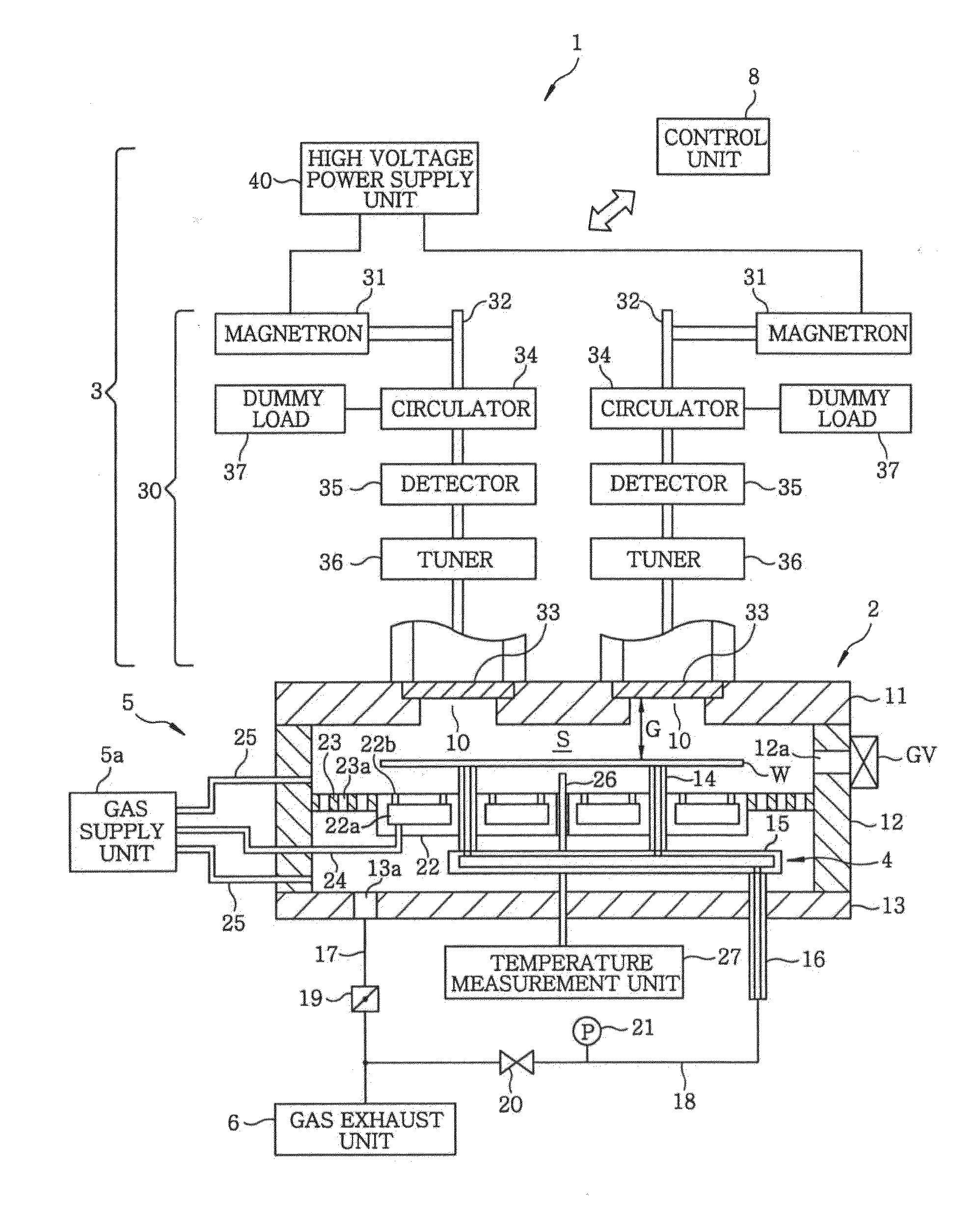
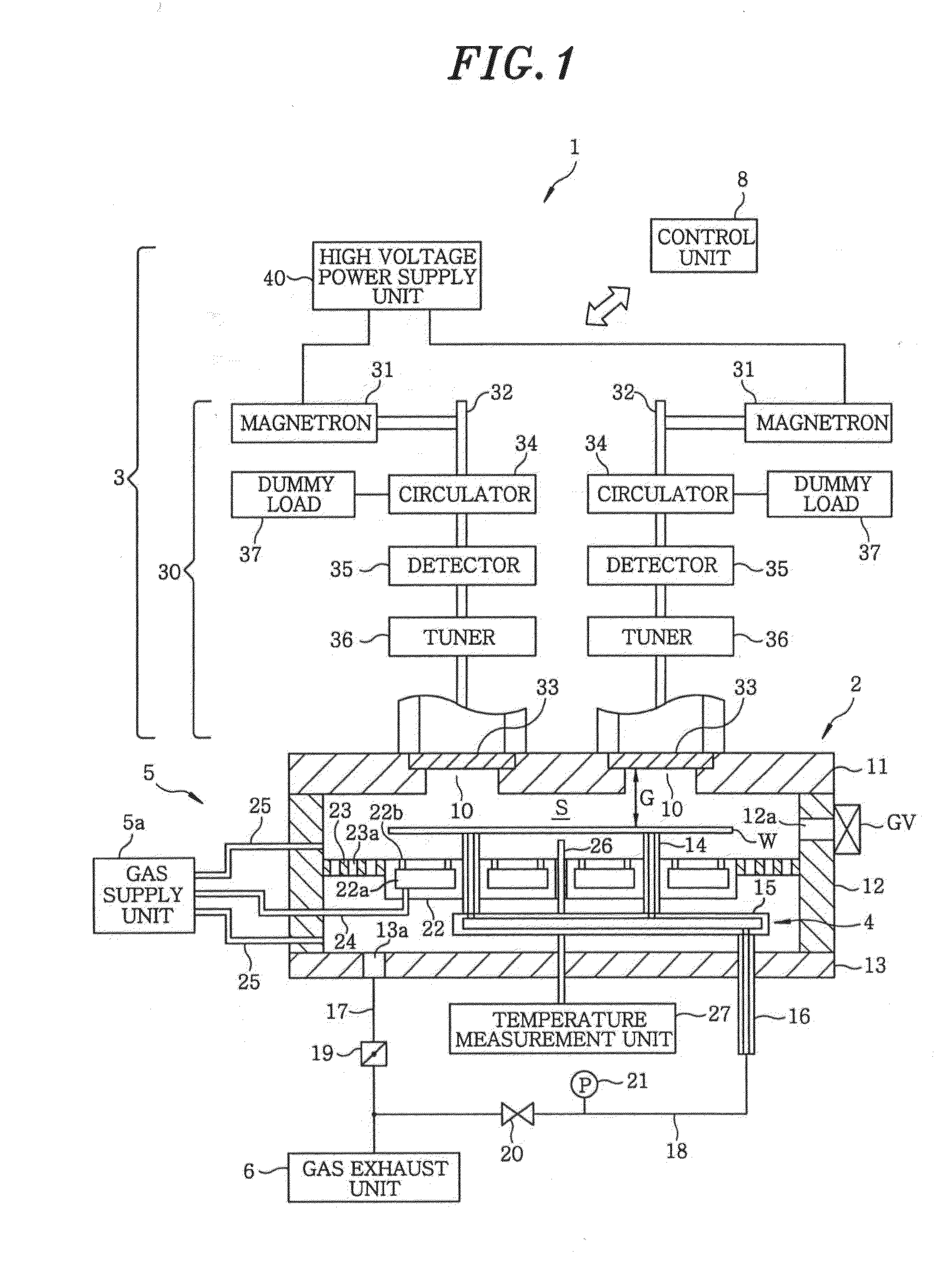
[0041]First, a schematic configuration of a microwave heating apparatus in accordance with a first embodiment of the present invention will be described with reference to FIG. 1. FIG. 1 is a cross sectional view showing a schematic configuration of the microwave heating apparatus in accordance with the present embodiment. The microwave heating apparatus 1 of the present embodiment performs an annealing process by irradiating microwaves to, e.g., a semiconductor wafer (hereinafter, simply referred to as “wafer”) for manufacturing semiconductor devices through a series of consecutive operations.
[0042]The microwave heating apparatus 1 includes: a processing chamber 2 accommodating a wafer W as a target object to be processed; a microwave introducing unit 3 for introducing microwaves into the processing chamber 2; a supporting unit 4 for supporting a wafer W in the processing chamber 2; a gas supply mechanism 5 for supplying a gas into the processing chamber 2; a gas exhaust unit 6 for ...
second embodiment
[0143]Next, a microwave heating apparatus in accordance with a second embodiment of the present invention will be described with reference to FIGS. 10 and 11. FIG. 10 is a cross sectional view showing a schematic configuration of a microwave heating apparatus 1A of the present embodiment. FIG. 11 explains a rectifying plate 23A of the microwave heating apparatus 1A of the present embodiment which serves as a microwave reflection mechanism.
[0144]The microwave heating apparatus 1A of the present embodiment includes a processing chamber 2 for accommodating a wafer W as a target object to be processed; a microwave introducing unit 3 for introducing microwaves into the processing chamber 2; a supporting unit 4 for supporting the wafer W in the processing chamber 2; a gas supply mechanism 5A for supplying a gas into the processing chamber 2; a gas exhaust unit 6 for vacuum-evacuating the processing chamber 2; and a control unit 8 for controlling the respective components of the microwave ...
third embodiment
[0154]Hereinafter, a microwave heating apparatus in accordance with a third embodiment of the present invention will be described with reference to FIGS. 12 to 14. FIG. 12 is a cross sectional view showing a schematic configuration of a microwave heating apparatus 1B of the present embodiment. FIG. 13 explains a state in which a microwave introducing adaptor 50 serving as an adaptor member having a waveguide for transmitting microwaves is installed at the ceiling portion 11. FIG. 14 explains grooves formed at the microwave introducing adaptor 50.
[0155]The microwave heating apparatus 1B of the present embodiment performs annealing by radiating microwaves to the wafer W for manufacturing semiconductor devices through a plurality of consecutive operations. In the following description, the difference between the microwave heating apparatus 1B of the present embodiment and the microwave heating apparatus 1 of the first embodiment will be described. In the microwave heating apparatus 1B ...
PUM
 Abstract
Description
Claims
Application Information
 - R&D
- Intellectual Property
- Life Sciences
- Materials
- Tech Scout
- Unparalleled Data Quality
- Higher Quality Content
- 60% Fewer Hallucinations
Browse by: Latest US Patents, China's latest patents, Technical Efficacy Thesaurus, Application Domain, Technology Topic, Popular Technical Reports.
© 2025 PatSnap. All rights reserved.Legal|Privacy policy|Modern Slavery Act Transparency Statement|Sitemap|About US| Contact US: help@patsnap.com