Coded aperture beam analysis method and apparatus

a beam analysis and coded aperture technology, applied in direction finders, direction finders using radio waves, instruments, etc., can solve the problems of no one having previously proposed rf digital beamforming, the matrix of rf switches is expensive to implement, and the additional bits (below one bit) will not improve radar performance, so as to achieve the effect of low probability of interception

Active Publication Date: 2013-07-04
HRL LAB
View PDF5 Cites 79 Cited by
  • Summary
  • Abstract
  • Description
  • Claims
  • Application Information

AI Technical Summary

Benefits of technology

[0013]Another advantage of this technology in a radar implementation is that transmitted RF energy is not required to be focused into a high gain beam, but instead may be radiated over a wide field of view. This produces a radar signal with a low probability of interception by electronic sensors.

Problems solved by technology

This approach differs from the present technology because it requires a complex matrix of RF switches that is costly to implement; it only requires a set of N single bit modulators inserted between the antenna elements and the summation network in a receiving application.(ii) U.S. Pat. No. 7,224,314 describes a reflectarray with each antenna element containing switching devices that vary the reflection impedances of the elements.
It is believed that no one has previously proposed RF digital beamforming by coding an antenna array aperture with single bit modulators.
Conventional phased array antennas place multi-bit phase shifters behind each element to form sharp transmit or receive beam patterns for a single measurement through constructive and destructive interference of the element fields.
Under these conditions, adding additional bits (beyond one bit) will not improve radar performance since single bit phase shifter control is sufficient to obtain a linearly independent set of measurements that may be “inverted” to estimate the antenna element signals and then processing these signals to produce digitally formed beams.
Conventional phased array radar antennas contain substantial microwave electronics (e.g., multi-bit phase shifters and variable gain amplifiers) at each antenna element, resulting in very high cost and high power dissipation.
Furthermore, a conventional phased array must obtain range and Doppler estimates for each beam position sequentially, resulting in a long acquisition time for high gain beams covering a wide field of view.

Method used


Image

  • Coded aperture beam analysis method and apparatus
  • Coded aperture beam analysis method and apparatus
  • Coded aperture beam analysis method and apparatus

Examples


Embodiment Construction

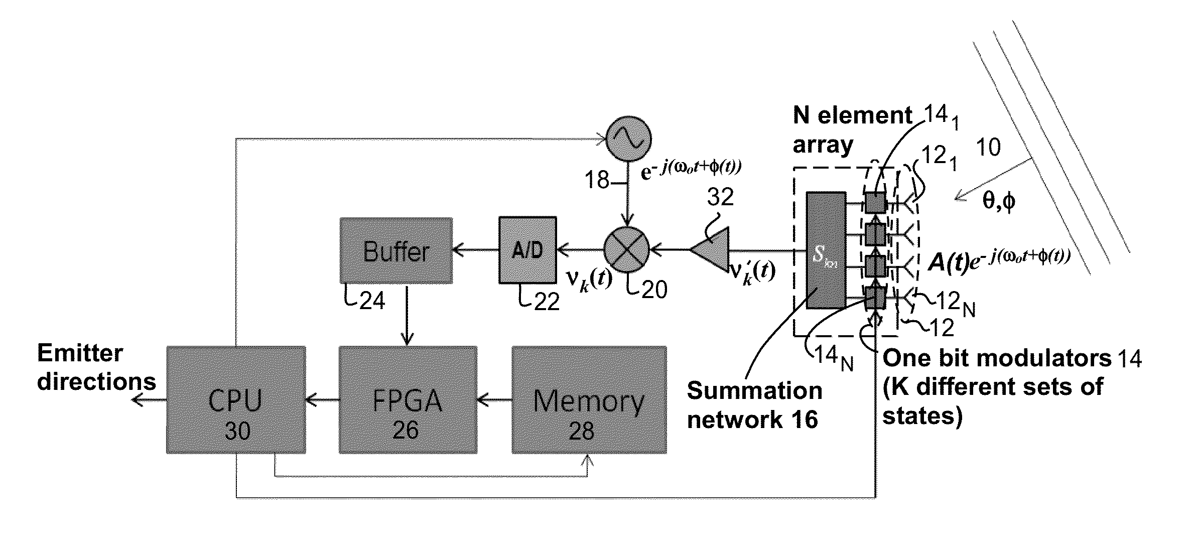
[0032]The coded aperture beam forming techniques disclosed herein may be used in a number of applications, including radio direction finding and radar, where a repetitive signal occurs. An embodiment of radio direction find using aperture beam forming techniques is first described and later several embodiments of radar using aperture beam forming techniques are described thereafter.

[0033]A “repetitive” signal f(t) is periodic in time and therefore satisfies f(t)=f(t+T), where T is the repetition period. Although this definition strictly applies only to signals of infinite duration (which do not occur in practice), the term “repetitive” is commonly used to describe signals where this condition applies over a finite period of time, but of significant duration for the system at hand. Repetitive signals may include pulsed radar waveforms, the carrier of many communication signals (e.g., AM and / or FM radio), and synchronizing signals transmitted by communication systems, all of which ex...


PUM


Abstract

A method and apparatus for determining the range, radial velocity, and bearing angles of scattering objects reflecting RF signals or for determining the range, radial velocity, and bearing angles of sources RF signals. An array of antenna elements is utilized, the array of antenna elements each having an associated two state modulator wherein transmitted and/or received energy is phase encoded according to a sequence of multibit codes, the bits of the multibit codes each preferably having two states with approximately a 50% probability for each of the two states occurring within each given multibit code in said sequence of multibit codes, thereby allowing the determination of range, radial velocity, and bearing angles through digital computation after the scattered signals have been received.

Description

CROSS REFERENCE TO RELATED APPLICATIONS [0001]This application claims the benefit of U.S. Provisional Patent Application Ser. No. 61 / 580,997 filed Dec. 28, 2011, entitled “Coded Aperture Beam Analysis Method and Apparatus”, the disclosure of which is hereby incorporated by reference.[0002]This application is also a continuation-in-part of U.S. patent application Ser. No. 13 / 490,607 filed Jun. 7, 2012, entitled “Coded Aperture Beam Analysis Method and Apparatus”, the disclosure of which is also hereby incorporated by reference.TECHNICAL FIELD [0003]This technology reduces the time required for a phased array radar to form estimates of range, radial velocity, and bearing angles of scattering objects over a wide field of view.BACKGROUND [0004]Prior art direction finding methods include:[0005](i) A conventional electronic support measure typically utilizes a small sparse array (e.g., 16 elements) of broadband antennas (e.g., spirals) that are non-uniformly spaced, each equipped with a s...

Claims


Application Information

Patent Timeline
Patent Type & Authority Applications(United States)
IPC IPC(8): G01S3/72
CPCG01S3/72G01S2013/0245G01S13/66G01S3/46
Inventor LYNCH, JONATHAN J.
Owner HRL LAB
Why Eureka
Try Eureka